Do you have a question about the Inter-m CA-8220 and is the answer not in the manual?
Guidance on setting up the mixer and handling packaging materials.
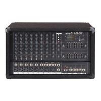
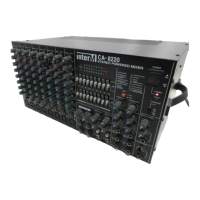
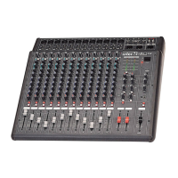
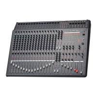
Details controls for mono input channels, including EQ and level adjustments.
Visual indicators for signal level and clipping on each channel.
Controls the main signal level for each channel sent to master and effects buses.
Adjusts the perceived position of a channel's sound in the stereo field.
Controls signal level sent to Effect Send 1 and Monitor bus.
Controls signal level sent to Effect Send 2 and internal DSP.
Three-band EQ (High, Mid, Low) for individual channel tone shaping.
Adjusts input sensitivity for optimal signal levels on MIC and LINE inputs.
Connects line-level audio sources via 1/4" phone jacks.
Connects microphones via XLR, supports phantom power.
Displays output signal levels for monitoring the master mix.
Shapes the overall program output frequency response.
Controls overall stereo output volume for speakers and headphones.
Outputs the summed stereo signal for external devices.
Allows external signal input, bypassing internal EQ and outputs.
Adjusts levels of tape deck signals to monitor and effect sends.
Manages signal levels for tape deck recording and playback.
Connects to tape decks for recording and playback signals.
Controls the built-in digital signal processor for effects.
Adjusts the overall output levels of effect mixes.
Receives signals from external effect units.
Sends effect mix signals to external devices.
Turns the unit's power supply on and off.
Indicates when the amplifier protection circuit is active.
Controls and indicates phantom power for microphones.
Adjusts levels of returned effect signals to the main mix.
Controls overall monitor mix output levels.
Outputs monitor mix signal to external speakers.
Adjusts the volume level for headphones.
Provides stereo output for headphones.
Describes rear panel speaker and AC input connections.
Important advice for connecting audio sources to the mixer.
Guidance on effectively using channel EQ controls for tone shaping.
Advice on using the graphic equalizer for sound shaping and feedback control.
Guidelines and restrictions for connecting speaker systems to the mixer.
Details on the built-in digital effects and their parameters.
Technical electrical specifications of the mixer, including power and frequency response.
General specifications such as power source, weight, and dimensions.
Details input connectors, impedance, and nominal levels.
Details output connectors, impedance, and nominal levels.
| Channels | 8 |
|---|---|
| EQ per Channel | 3-band (High, Mid, Low) |
| Frequency Response | 20Hz - 20kHz |
| Microphone Inputs | 8 (XLR) |
| Line Inputs | 8 (1/4" TRS) |
| Phantom Power | +48V |
| Input Impedance | Mic: 2k ohms, Line: 10k ohms |
| Power Source | AC |