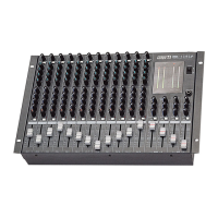
MIC LINE MIXER
6
LM-6414
16. CUE SWITCHES
T
hese buttons are used to select the associated output bus as active, sending signals routed to that bus to the
rear-panel output connector.
17. OUTPUT MONITOR SELECTOR
These buttons are used to select the output source for monitoring and headphones output.
18. HEADPHONE OUTPUT
This is a balanced 1/4” stereo jack for connection of headphones for monitoring the outputs of the busses as
selected by the Output Monitor Selector (17), or to monitor input channels where PFL switches (11) are
selected.
19. HEADPHONE GAIN
This knob controls the output level of the headphone jack.
20. POWER INDICATOR
This LED is lit when the power is switched on to the unit.
21. AUX1/2 RETURN GAIN CONTROLLER
This is a gain controller for the returned signal of AUX1/2 RETURN from external device such as reverb
processor.
22. AUX1/2 RETURN PAN CONTROLLER
This is a PAN level controller for the returned signal of AUX1/2 RETURN from external device such as reverb
processor.
23. OUTPUT LEVEL DISPLAY SELECTOR
ON : STEREO L/R, PFL, MON, Level
OFF : BUS 1, 2, 3, 4
24. AUX1/2 SEND GAIN CONTROLLER
These are gain controller for each input channel audio to send AUX1/2 SEND for external device such as
effector.