STEREO MODE, BRIDGED MODE AND PARALLEL MODE
55
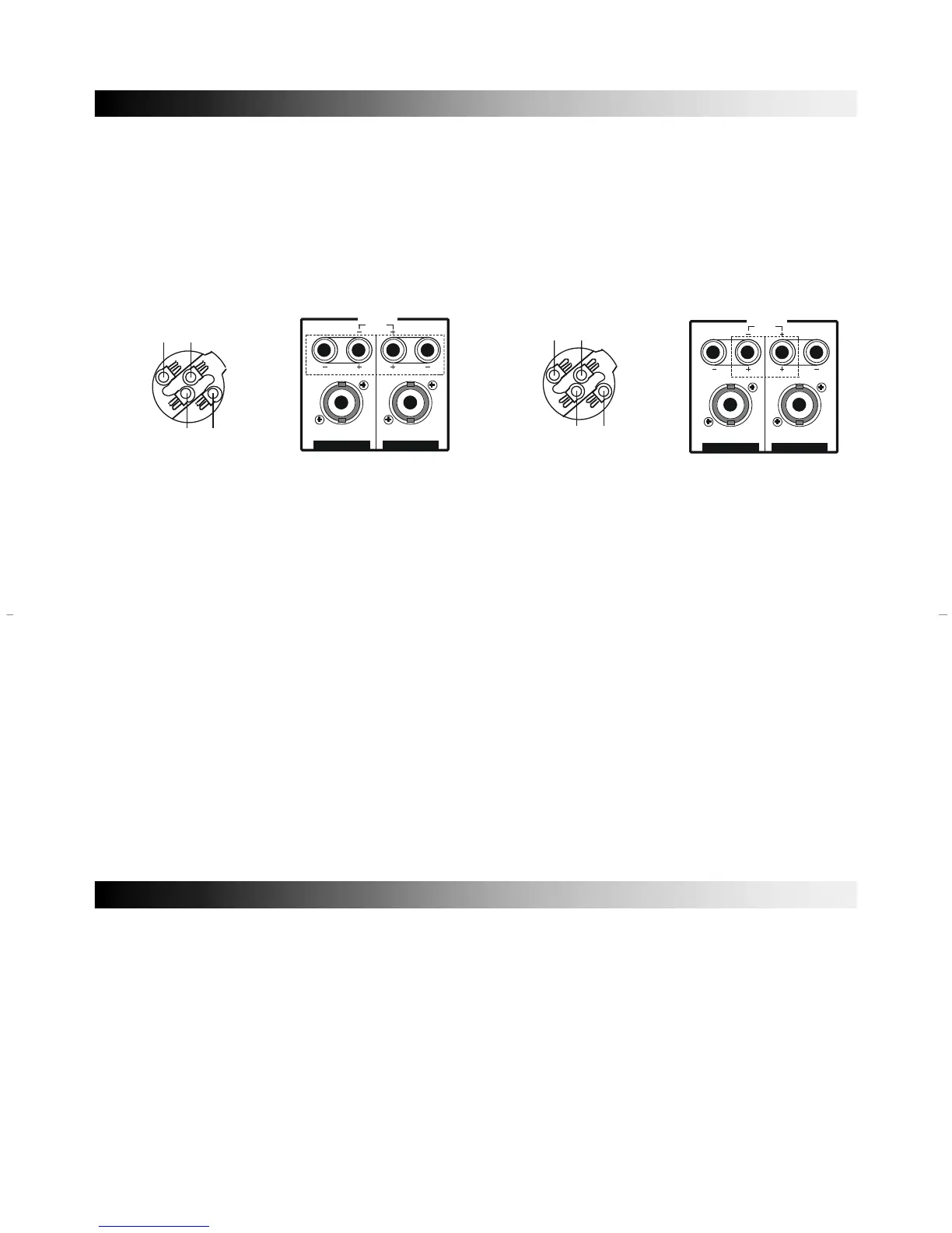
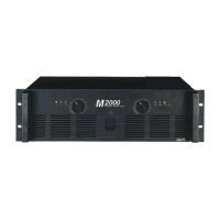
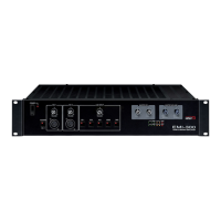
2. OUTPUT TERMINALS
Output terminals are dual five-way binding posts and speaker connectors. Do not parallel the two
outputs of each channel by connecting them (together, or parallel them) with any other amplifier output.
* When speakers are connected through speaker, please make sure correct connection of each
pin, and refer speaker pin number.
• STEREO MODE • BRIDGED MODE
The minimum impedance for the connected speaker system is specified in “Speaker Im-
penance” on page 6.
3. CIRCUIT BREAKER
When the circuit breaker is cut, push to reset again. In case of occurring trouble to the set by
means of overload or error, circuit breaker will protect the set from trouble by breaking AC power
source.
4. AC POWER CORD
Plug this AC input cord into AC outlet.
5. MODE SELECTOR
Bridged mono or parallel operation are easily accessed by the slide switch. The input is applied
channel one only the corresponding front panel control is used to set the level, please refer
bridged mono operation or parallel operation.
6. FANS
The fans should be kept free of all obstructions and be accessible to cool fresh air when
• STEREO MODE
In this mode, channels 1 and 2 operate independently (typical stereo amplifier). Channel 1 input
signal feeds channel 1 power amp, and channel 2 input signal feeds channel 2 power amp. In this
mode, the minimum speaker impedance per channel is 4Ω.
• BRIDGED MODE
In this mode, channels 1 and 2 are bridged together and work as one mono amplifier. In this
mode, the minimum speaker impedance is 8Ω.
• PARALLEL MODE
In this mode, channels 1 and 2 are operate two mono amplifier. In this mode channel 1 input signal
feeds channel 1 and channel 2 power amp, the minimum speaker impedance per channel is 4Ω.