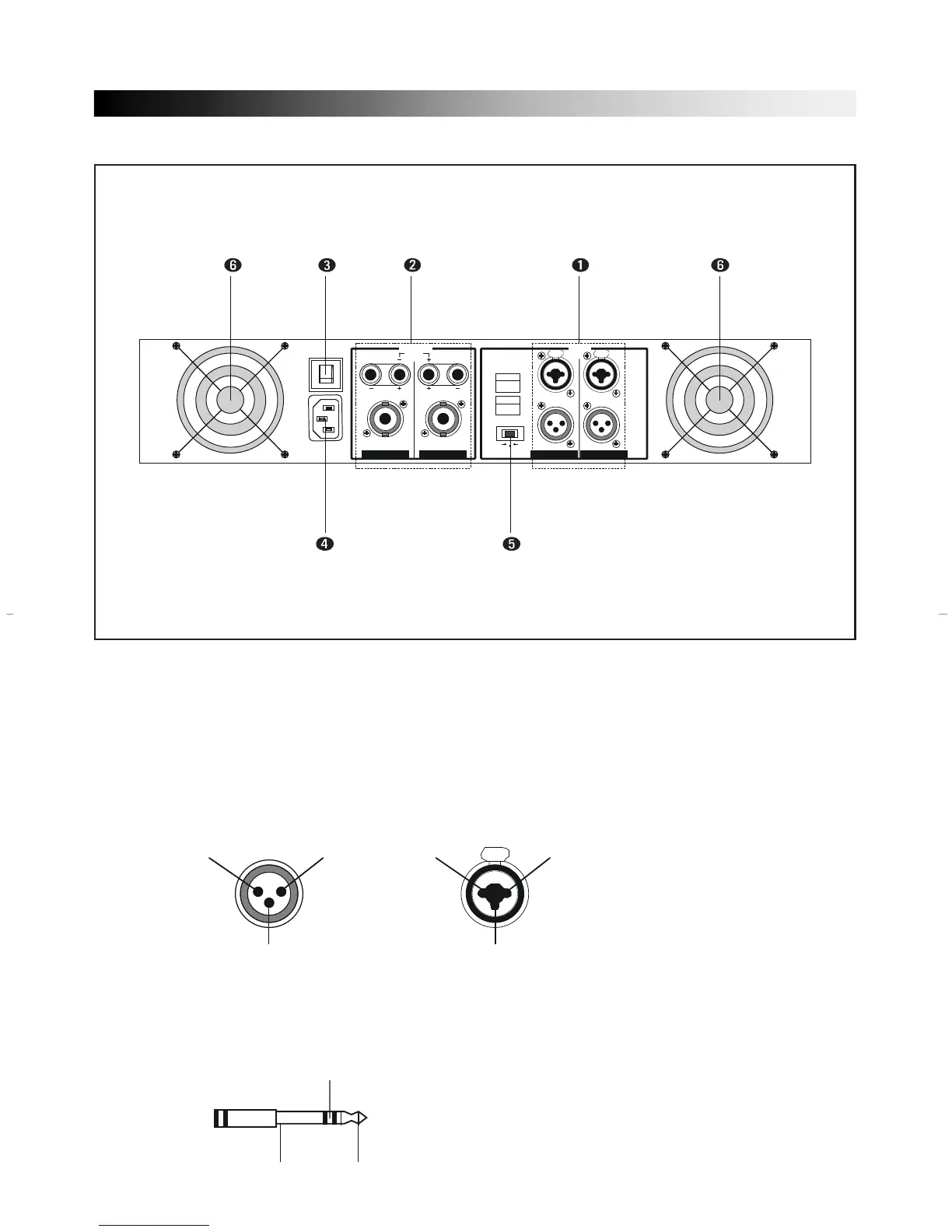
EasyManuals Logo

Inter-m M-1000 User Manual

Inter-m M-1000
12 pages
To Next Page IconTo Next Page
To Previous Page IconTo Previous Page
Page #5 background imageLoading...
Page #5 background image
44
REAR PANEL CONTROLS
1. INPUT TERMINALS (CHANNEL 1, 2)
Input connectors are provided both balanced combination jacks.
Channel 1 input terminal is used in Bridge mode and parallel mode.
• XLR-TYPE CONNECTOR
They are wired pin 1-ground, pin 2-hot (+), and pin 3 cold (–).
• PHONE JACK
They are wired tip-hot (+), ring-cold (–), and sleeve-ground.
10A/250V
PUSH TO RESET
~AC INPUT
230V 50Hz, 770W
OUTPUT
BRIDGED
(8~16)
BRIDGED
PARALLEL
STEREO
INPUT
BALANCED
0dBm
CH 2
TRS
BALANCED
•TIP=HOT
•RING=COLD
•SLEEVE=GND
XLR
BALANCED
•3=COLD
•2=HOT
•1=GND
PUSH
BALANCED
0dBm
(4~8)
(4~8)
(4~8)
(4~8)
PUSH
CH 1
CH 2
CH 1
2
1
3
HOT
GROUND
COLD
PUSH
2
1
3
HOT
GROUND
COLD
COLD
GROUND
HOT
XLR MALE COMBINATION
FOR LINK
FOR INPUT

Questions and Answers:

Question and Answer IconNeed help?

Do you have a question about the Inter-m M-1000 and is the answer not in the manual?

Inter-m M-1000 Specifications

General IconGeneral
BrandInter-m
ModelM-1000
CategoryAmplifier
LanguageEnglish

Related product manuals