7
PX-0288
8x8 AUDIO MATRIX
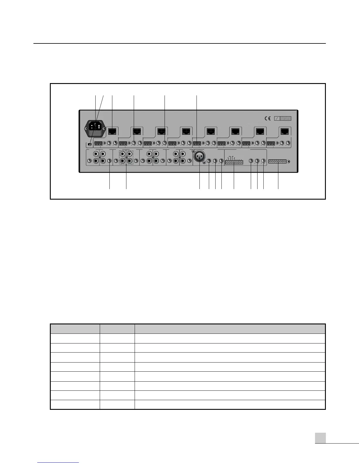
PX-0288 Rear Panel
PX-0288 Rear Panel
1. AC MAINS POWER INPUT
This is the AC MAINS input receptacle which accepts the detachable AC power cable. Connect only to an
appropriate AC mains power source.
2. PHANTOM POWER SWITCH
When this switch is in the ON position, Phantom Power(DC +24V) will be provided between pin 2 and pin 3
of the PAGING MIC INPUT XLR-type jack. If you do not use microphones that require phantom power, be
sure this switch is in the OFF position.
3. REMOTE CONTROL CONNECTOR
One remote control (either the LM-88 or the PS-88) may be connected to each output zone. Each remote will
need to be given an address (or identity) which is accomplished via DIP switches on the remote. Each remote
must be addressed according to the zone it controls. Do not give the same address to more than one remote.
- PIN Legend (RJ-45, UTP Cat5)
PHANTOM
10
0
10
0
www.inter-m.com
PGM 1
L
R
PGM 2
L
R
PGM 3
L
R
PGM 4
L
R
PGM 5
L
R
PGM 6
L
R
PGM 7
L
R
PGM 8
L
R
LEVEL LEVELLEVELLEVELLEVELLEVEL LEVEL LEVEL
PAGING MIC IN
LEVEL
TREBLE BASS
LEVEL
REMOTE MIC IN
S
N
ON OFF
TREBLE
OUTPUT
BASS TREBLE
OUTPUT
BASSTREBLE
OUTPUT
BASSTREBLE
OUTPUT
CONTROL
BASS TREBLE
OUTPUT
BASS TREBLE
OUTPUT
BASS TREBLE
OUTPUT
BASS TREBLE
OUTPUT
BASS
PHANTOM
CONTROL
CONTROL
CONTROL
CONTROL
CONTROL
CONTROL
CONTROL
ZONE 1
ZONE 7 ZONE 8ZONE 2 ZONE 3 ZONE 4 ZONE 5 ZONE 6
FIRE ALARM
CONTACT CLOSURE
5678GND4321
12
12 1212
TREBLE BASS
1212 1212
1212 12121212 12121212 12121212 12121212 12121212 12121212 12121212 1212
10 10 10 10 10 10 10 10
0000000 0
+
G
+
G
+
G
+
G
+
G
+
G
+
G
+
G
CONTROL
A-GND
Rx-Rx+Tx-Tx+
AUD-
AUD+ DC 24V
D-GND
32
7
1 64 5
8 101112 1415169 13 17
PIN Number
1
2
3
4
5
6
7
8
PIN NAME Functions
Rx- RS-422 Negative Receive
Rx+ RS-422 Positive Receive
Tx- RS-422 Negative Transmit
Tx+ RS-422 Positive Transmit
D-GND Digital Ground
DC Output Power Supply
Audio+ Balanced Audio Hot
Audio- Balanced Audio Cold