1
Electrical Adjustment Procedure 1
Specifications
2
Electrical Parts List
3, 4
Top and Bottom View of P.C. Board
5, 6
Wiring Diagram 7
Block Diagram 8
Schematic Diagram 9, 10, 11, 12
Exploded View of Cabinet & Chassis / Mechanical Parts List
13, 14
Ass’y Drawing
15, 16
CONTENTS
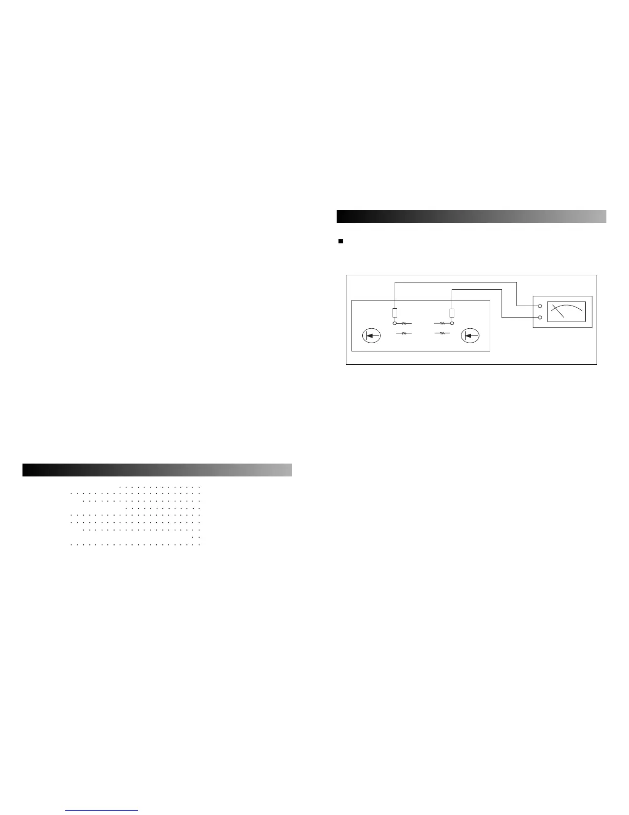
IDLE CURRENT
A. Setting
Set the master volume minimum.
B. Connection
C. Adjustment
– Adjust VR301 so that the current through the R237, R236, R342, R343 become 10 milliampere.
– When that voltage across the “TP1” to “TP2” becomes 10 millivolt, the current becomes 10
milliampere.
ELECTRICAL ADJUSTMENT PROCEDURE
 Loading...