Interflex Datensysteme GmbH 6/8
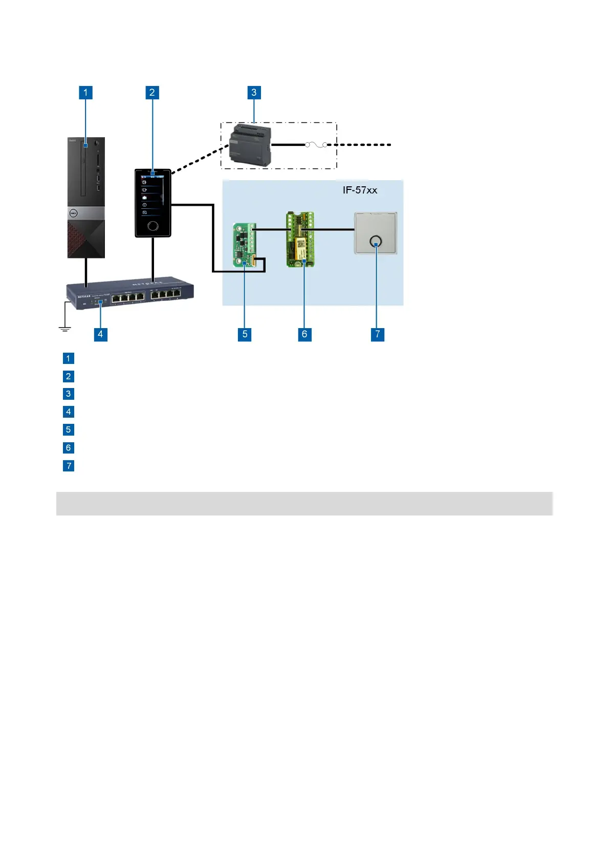
3 Integrating Terminals into the System
Server with time recording software, e.g. IF-6020 or IF-6040
IF-57xx / IF-5835 master terminals
External power supply (optional) with a mounting rail power supply unit and fuse protection
PoE device: Switch or power injector
Interface expander
I/O controller board for direct connection to slave terminals
IF 800 slave terminal
Connect the components as shown in the figure.
As opposed to LEGIC and MIFARE reading technologies, the reading unit with SimonsVoss Active
Technology (SVP) must be configured for the respective customer settings.
Points to note on the compliance with the required EMC values
Check if there is functional grounding on the PoE device. Ground PoE devices without functional
grounding via existing soldering lugs or screw terminals.
Observe the notes under Cable lengths and cable types (on page 2).
Observe the standards applicable to electrical installations.
The device may only be operated via electrical systems that comply with current national standards.
 Loading...