Interflex Datensysteme GmbH 3/13
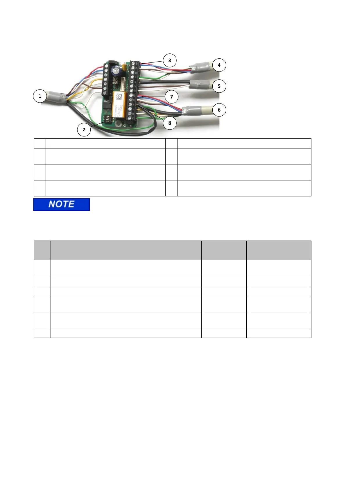
6.2 Connecting the I/O Controller Board
1 Cable to IF-80x terminal 5 RS485 data cable
2 Address switch 6 Control line with 2 floating inputs and 1 relay output.
Max. switching power: 30 V, 2 A
3
Here, the power supply is connected with one line
pair each.
7 Relay output. Here, the cable is connected with one line
pair each.
4 Cable to power supply. Connection voltage: 18 to
max. 24 V AC/DC
8 Functional grounding and shield are connected to a
terminal together.
Since the cable run to the IF-80x terminal is usually very long, we recommend
connecting the power supply and the relay contact with one cable pair each.
6.3 Function of the Cables and Cable Types
Function of Cable Max. Length Recommended Cable
1 230 VAC power supply to 20 VAC, 1.5 A power transformer
(order no. 41-10106)
NYM 3 x 1.5 mm²
2 Low-voltage cable J-Y(ST) Y 4x2x 0.6 mm
3 Ethernet/patch cable from server to switch/hub max. 100 m Category 5
4 Ethernet/patch cable from switch/hub to controller/master
terminal
max. 100 m Category 5
5 Shielded cable from IF-80x terminal to controller/master
terminal
max. 100 m J-Y(ST) Y 4x2x 0.6 mm
6 RS485 bus cable max. 1200 m J-Y(ST) Y 4x2x 0.6 mm