6 TruPortal IP-based Single Door Controller Quick Reference
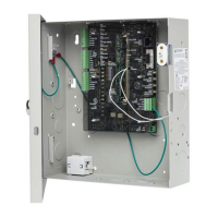
Figure 9: IPSDC Board Layout
The following table lists the items shown in Figure 9.
Callout Description Callout Description
1 IPSDC board with overlay 11 Network (Ethernet) port J10
2 Reader In (Access) J1 12 Console port J9
3 Door Contact, Request to Exit (RTE) and
Strike Relay J2
13 Enclosure tamper W5
4 Strike Voltage Select W2 14 Boot Mode switch SW4
5 Custom Wiegand Card Format DIP switch
SW1
15 Hardware Reset switch SW5
6 Reader Out (Egress) J3 16 Shutdown Request switch SW6
7 DIP Switch 2 (set all to OFF) SW2 17 Restore Defaults switch SW7
8 Status LEDs typical 18 Aux Power Input 24 VDC
Note: Jumpers between pins 3 and 4, and pins 4
and 5 must remain in place.
9 UCSIMMPlus Module 19 Fire Alarm Control Panel (FACP) Input J6
Note: The IPSDC does not support FACP so
this jumper must remain in place.
10 IPSDC board mounting holes
 Loading...