Do you have a question about the Interlogix CDC4 and is the answer not in the manual?
Discusses legal limitations on manufacturer liability for product use and installation.
Explains warning, caution, and note message types used for hazard and information communication.
Lists required qualifications for technicians using the manual for installation and configuration.
Overview of the chapter's content on installing the CDC4 door controller.
Covers general recommendations and information for the installation process.
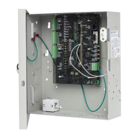
Details the physical enclosure of the CDC4, including mounting points and dimensions.
Instructions for mounting the CDC4 printed circuit board within the enclosure using standoffs.
Explains how to connect the transformer output lead and steps for replacing the transformer.
Details how to replace the fuse protecting the transformer from over-current conditions.
Covers safety regulations for earthing the enclosure base and door using provided cables.
Describes optional accessories like guard plates, tamper kits, and transformer retainers.
Explains tamper monitoring and provides steps for installing the tamper bracket and switch.
Instructions on how to install various devices using standoffs within the enclosure.
Detailed diagram and labeling of the CDC4 printed circuit board components and connectors.
States that servicing is restricted to qualified personnel and provides torque specifications.
Details safe connection of AC mains supply, emphasizing regulations and circuit breakers.
Explains that only qualified installers should replace batteries due to configuration impact.
Provides guidelines for proper battery terminal wiring, connection, and polarity verification.
Covers physical mounting instructions, including wall support strength and surface requirements.
Recommendations for wiring, cable entry, and separation of low voltage/mains cables.
Details earthing procedures for cabinets, buildings, and managing earth potential variations.
Provides guidelines for connecting shielded cables for noise reduction and data integrity.
Explains how to use the four-segment DIP switch to set the CDC4 address as an expander.
Details various connection types including power, batteries, and data bus interfaces.
Explains the use of bus termination resistors for impedance matching and noise minimization.
Describes options for powering door locks and relevant relay wiring configurations.
Explains how CDC4 monitors input circuits for various states like active, normal, or tamper.
Describes connecting Wiegand devices, including typical wiring for smart card readers.
Details adding outputs using expansion cards and mapping physical outputs to system numbers.
Lists LEDs on the PCB and their functions indicating the status of CDC4, bus, and Ethernet.
Steps to power up the controller, check connections, DIP switches, and system ready LED.
Instructions to reset the CDC4 to factory default state, erasing all programming.
Procedure to reset the USB communication path using a test link on the CDC4 panel PCB.
Explains capacitor storage maintains clock and logs for up to 5 days without power.
Details the current draw of the standalone board under normal operating conditions.
Specifies maximum current draw limits for user devices and details on-board fuse protection.
Discusses the operating temperature range and the need to derate user current above +40°C.
Recommendations for system earthing, Ethernet, data bus cabling, and power supply for bus devices.
Lists technical specifications including power, Ethernet, environmental, and fuse details.
Introduces the chapter which lists and describes CDC4 Door Controller functionality.
An alphabetic list of CDC4 functions with references to their description pages.
Details Standard mode (panel communication) and Extended mode (direct IP connection).
Explains CDC4 door support, numbering, and per-expander address configurations.
Describes new lock types like Strike and Maglock, with associated inputs, outputs, and timers.
Illustrates simple door unlock and unlock with input monitoring scenarios.
Explains interlocking methods for doors on the same or external controllers.
Defines regions for access control areas, used for anti-passback and high security.
Functionality to prevent users from entering a region twice without leaving, with access options.
Configuration for High Security Regions requiring a minimum number of High Security Users.
Enables region-based alarm control where users leaving/entering set/unset areas.
Describes using panel schedules for door groups, override schedules, and RTE schedules.
Allows programming up to 100 door schedules for flexible locking and unlocking operations.
Tool for activating events based on programmed conditions, allowing up to 48 macros.
Defines levels for door alarm control analogous to user groups, assignable to doors.
Explains using macros to indicate exit time via a buzzer for readers not connected to the main panel.
Details supported protocols like OSDP, SALLIS, and Aperio for devices connected to CDC4 buses.
Options for specifying device connection: On-board, DGP, or RAS, and how they are addressed.
Configures mapping of physical inputs/outputs to input/output numbers for Advisor Advanced.
Defines priority for door states and methods for overriding default door states.
Configures a lockout period after a 'Door random bit' event, restricting access to privileged users.
Describes using readers for time and attendance functions, specifying clocking on/off behavior.
Introduces the chapter on using Advisor Advanced programming menus to program the system.
A step-by-step guide for programming the CDC4 Door Controller using Downloader.
Instructions on connecting Downloader to the Advisor Advanced panel and adding the CDC4.
Recommendations for upgrading the Door Controller firmware to the latest version.
Steps to configure Ethernet and IP communications paths for the CDC4 in Extended mode.
Introduces the chapter, which details all programming menu entries for the CDC4 Door Controller.
Describes programming the Door Controller via the Expander devices form and its associated tabs.
Tab for programming general controller options, with fields explained in subsequent sections.
Shows and allows editing of input mappings, including input type and associated door.
Lists and allows editing of output mappings, including output type and location.
Assigns keypads and readers (RASs) to the CDC4, including settings for name, type, and polling.
Assigns expanders (DGPs) to the CDC4, including settings for name, type, and polling.
Configures IP communication paths for management software, specifying protocol, server, and ports.
Allows defining up to 48 macros for automating events based on programmed conditions.
Configures door schedules, including enabled status, dates, active days, start time, and actions.
Defines High Security User (HSU) configurations for regions, including limits and outputs.
Manages alarm control levels, linking them to schedules and areas for arming/disarming permissions.
Defines regions as access control areas, used for anti-passback and high security functions.
Covers general door settings, hardware options, access control, and reader configurations.
Configures hardware options for a door, including lock types and device locations.
Configures access options for a door, including unlock times and card/PIN requirements.
Configures options for shunting, Request to Exit (RTE), and anti-passback for doors.
Assigns door readers (IN/OUT) to doors, with settings for name, enabled status, and card format.
Configures IN and OUT reader alarm control for arming/disarming the system, including badge methods.
Covers programming door groups and individual user access and credentials.
Instructions for programming door groups, either inheriting from Advisor Advanced or creating new ones.
Instructions for adding new users or configuring existing users' access and credentials.
Introduces the chapter on resolving hardware and configuration problems, and recovering lost access.
Lists common issues with door controllers not communicating or going offline.
Troubleshooting steps for door controller communication, reader status, and zone alarm issues.
Troubleshooting for remote expanders regarding Tx LED, Tx/Rx LEDs, and expander offline status.
Lists door-related macro events, their descriptions, and whether they are inputs or outputs.
Lists general macro events like area access, alarm, and controller status, with input/output types.
Provides numerical ranges for door-related events used as macro inputs or outputs.
Lists default settings for Access, Shunt, RTE, and Anti-Passback configurations.
Default assignments for lock outputs, door inputs, and RTE inputs across multiple doors.
Definition of controlling entry or exit from a security area through doors.
| Brand | Interlogix |
|---|---|
| Model | CDC4 |
| Category | Controller |
| Language | English |