Chapter 1: Installation
CDC4 Door Controller Installation and Programming Manual 3
General installation information
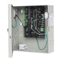
CDC4 housing
The housing with mounting holes (items 1) is shown in Figure 1 below.
All dimensions are given in mm.
Figure 1: CDC4 housing
(1) Enclosure wall mounting points
(2) Board mounting points (x178)
(3) Tamper switch bracket slots
(4) Tamper switch bracket mounting point
(5) Door close points
(6) Rear cable entry holes (x7)
(7) Mains terminal position (optional)
(8) Cable tie points (x34)
(9) Transformer bracket mounting points
(10) Transformer position
(11) Battery positions
INPUTS
1 C 2 C 3 C 4 C 5 C 6 C 7 C 8 C
RELAY EXPANDER PWR
ON
1 2 3 4
USB
ETHERNET
1
2
3
4
ADDRESS
1 2
TEST
LINKS
LINK
ACT
10/100
Mbps
HEART
BEAT
LOCK
PWR 1
BUS 1
EXPANDER SLOT 1
TERM
TERM
TERM
BUS 2 BUS 1
+12 - D+ D- +12 - D+ D-
Tx Rx
Tx Rx
LOCK
PWR 2
BUS 1
AC
BATT1
BATT2
AUX POWER
OUT
PANEL
TAMP
RELAY 1
RELAY 2
RELAY 3
RELAY 4
+
-
+
-
+12
-
+12 +12
-
-
S-
S+
D+
-
D-
T
C
+12 COM
NC
NO
0V
+12 COM
NC
NO
0V +1 2C OM
NC
NO
0V
+12 COM
NC
NO
0V
RX
TX
LICENCE KEY
~
~
(1) (2) (3) (4)(1) (5)
(6)
(6)
(8)
(1)
(9)
(10)
(1)
(11) (11)
258 mm
340 mm
520 mm
(5)
(7)