Chapter 1: Installation
4 CDC4 Door Controller Installation and Programming Manual
CDC PCB
Install six provided standoff board mounts for the PCB in the housing to position
the door controller PCB as shown in Figure 1 on page 3.
Caution: Make sure to use all six provided M3 x 10 pan head screws to fix the
board to the housing standoffs to avoid bending the PCB over. Refer to Figure 12
on page 13 for the mounting hole locations marked as item 1. On the physical
PCB, mounting holes are marked as MT1 to MT6.
Transformer
The transformer is pre-installed in the bottom left corner of the enclosure.
Caution: Fit the terminal block to the output lead of the transformer prior to
applying power.
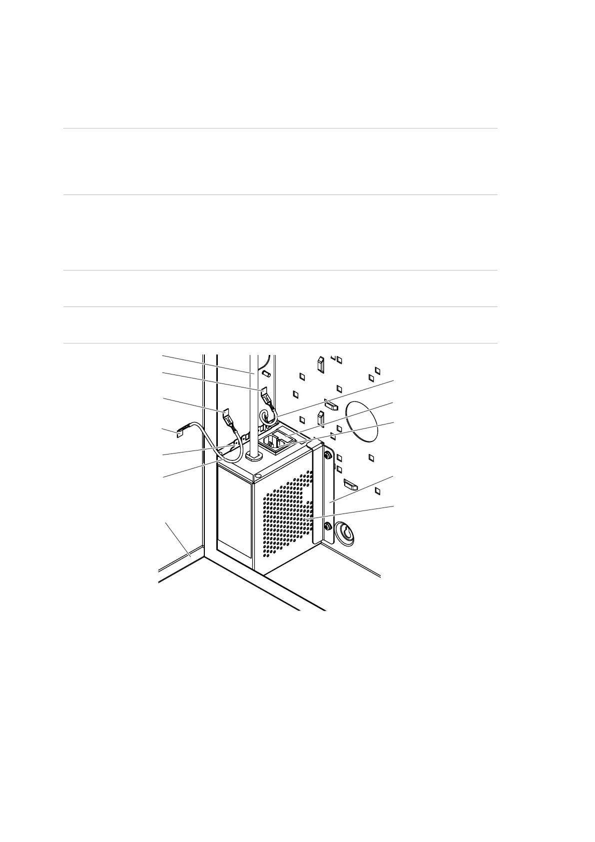
Figure 2: Transformer
(1) Output lead
(2) Earth tab (enclosure)
(3) Earth lead (transformer - enclosure)
(4) Earth tab (enclosure)
(5) Fuse holder
(6) Earth tab (door)
(7) Power Inlet
(8) Earth tabs for devices
(9) Earth lead (enclosure - door)
(10) Transformer bracket
(11) Door
(12) Transformer
The transformer has five tabs to provide an earth connection for the enclosure
and installed devices.
(1)
(2)
(4)
(6)
(8)
(9)
(11)
(3)
(5)
(7)
(10)
(12)