Chapter 1: Installation
CDC4 Door Controller Installation and Programming Manual 33
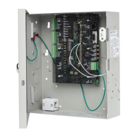
Powering up the door controller
Ensure the Advisor Advanced system bus is connected to the panel terminals
(Figure 12 on page 13, item 8), and ensure the CDC4 address is set correctly
(refer to “DIP switch settings” on page 23).
Ensure that jumpers on board are set correctly and that TEST LINKS are not
fitted.
After power-up, check the heart beat LED (Figure 12 on page 13, item 17). See
“LED indications” on page 32.
Note: Devices connected to the buses and powered by the door controller must
comply with “Output fusing and user current draw” on page 38.
The System ready LED (Figure 12 on page 13, item 36) indicate that CDC4 is
ready to accept programming. See “LED indications” on page 32.
Refer to Chapter 3 “Programming” on page 75 for information on configuring
CDC4.