EasyManua.ls Logo

Interlogix TruPortal TP-ADD-1DIP User Manual

Interlogix TruPortal TP-ADD-1DIP
9 pages
To Next Page IconTo Next Page
Page #1 background imageLoading...
Page #1 background image
P/N 460939301B • REV 01.00 • 30OCT13 1
TruPortal
IP-based Single
Door Controller (IPSDC)
Quick Reference
en-US
Introduction
The TruPortal IP-based Single Door Controller (IPSDC) provides
distributed processing for the interface of access control readers,
digital inputs, and outputs to the TruPortall System Controller.
The IPSDC is pre-configured to use Power-over-Ethernet (PoE),
using electrical power from Ethernet cabling, but can also be
configured to use an auxiliary power supply.
Packing List
IPSDC printed circuit board (PCB) assembly and overlay
Hardware kit
- Ground terminal lug
- SEMS screws
- Protection diodes for door strike wiring
- Metal Oxide Varistor (MOV) surge absorbers for door
strike wiring
- Ferrite for use with network cables
- 1K end-of-line resistors
Lock (quantity = 1)
Enclosure
Enclosure mounting template
Installation screwdriver
TruPortal IP-based Single Door Controller (IPSDC) Quick
Reference (this document)
Model Numbers
The IPSDC is available in the following configurations:
TP-ADD-1DIP: TruPortal single-door base kit. Consists of a
TruPortal IPSDC, installed in a UL-listed enclosure.
TP-ADD-1DIP-BRD: TruPortal IPSDC board only. Capable of
controlling one door. No enclosure or readers included.
Installation Procedure
To install the IPSDC, perform the procedures described in the
following sections, in the order in which they are presented.
1. Mount the enclosure.
2. Set the dual in-line package (DIP) switches.
3. Connect the reader(s) and inputs.
4. Connect the door strikes.
5. Connect the power.
6. Verify proper operation on power up.
7. Configure the IP address of the IPSDC and the IP address of
the System Controller (TP-SYS).
WARNING: Circuit board components are vulnerable to damage
by electrostatic discharge (ESD). ESD can cause
immediate or subtle damage to sensitive electronic
parts. An electrostatic charge can build up on the
human body and then discharge when touching a
board. A discharge can be produced when walking
across a carpet and touching a board, for example.
Before handling any board, make sure to dissipate
any charge by touching the ground. This discharges
any static electricity build-up.
WARNING: Do not apply power to any component during
installation. Damage to components may occur if
power is incorrectly applied.
Mounting the Enclosure
1. Using the template provided, mark and then drill the four
mounting holes.
2. Bolt the enclosure securely to the wall, using four #8 thread
lag bolts or equivalent.
Question and Answer IconNeed help?

Do you have a question about the Interlogix TruPortal TP-ADD-1DIP and is the answer not in the manual?

Interlogix TruPortal TP-ADD-1DIP Specifications

General IconGeneral
ModelTP-ADD-1DIP
CategoryController
CompatibilityTruPortal
Operating Voltage12 VDC
Voltage12 VDC
Operating Temperature32° to +120° F
Outputs1
CommunicationRS-485
Dimensions7.6 x 11.4 x 2.5 cm
Weight0.11 kg
Operating Humidity15 to 85%, non-condensing
Humidity15 to 85%, non-condensing
Inputs2

Summary

Product Overview and Installation

Model Numbers

Lists available IPSDC configurations and their contents.

Introduction

Describes the IPSDC's function in distributed access control systems.

Packing List

Itemizes components included in the IPSDC package for installation.

Installation Procedure Overview

Outlines the sequential steps required for installing the IPSDC unit.

Mounting the Enclosure

Provides instructions on how to securely mount the IPSDC enclosure to a wall.

System Configuration and Wiring

Setting DIP Switches

Guides on configuring input types and system settings using DIP switches.

Connecting Readers and Inputs

Details wiring for readers and digital inputs for door status monitoring.

Connecting Door Strikes

Explains how to wire door strike devices for access control functionality.

Power and Network Connectivity

Grounding and Safety Precautions

Covers essential grounding procedures and regulatory compliance for safe operation.

Connecting Power

Outlines methods for supplying power to the IPSDC unit.

PoE Power Connection

Step-by-step guide for connecting the IPSDC using Power-over-Ethernet.

Auxiliary Power Connection

Instructions for wiring an auxiliary 24 VDC power supply for the IPSDC.

Advanced Operations and Reference

IPSDC Configuration Steps

Detailed procedure for configuring IP addresses and controller settings via browser.

Safe Shutdown Procedure

Method for safely powering down the IPSDC unit during maintenance.

IPSDC Board Component Identification

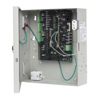
Identifies key connectors, LEDs, and switches on the IPSDC circuit board.

Wiegand Wiring Details

Specific wiring diagrams and pinouts for Wiegand readers.

LED and Switch Status

Explains the meaning of status LEDs and the functionality of board switches.

Technical Specifications

Lists the physical, environmental, and electrical specifications of the IPSDC.

Regulatory Compliance

Details compliance information for FCC, CE, and UL standards.

Related product manuals