TruPortal IP-based Single Door Controller Quick Reference 7
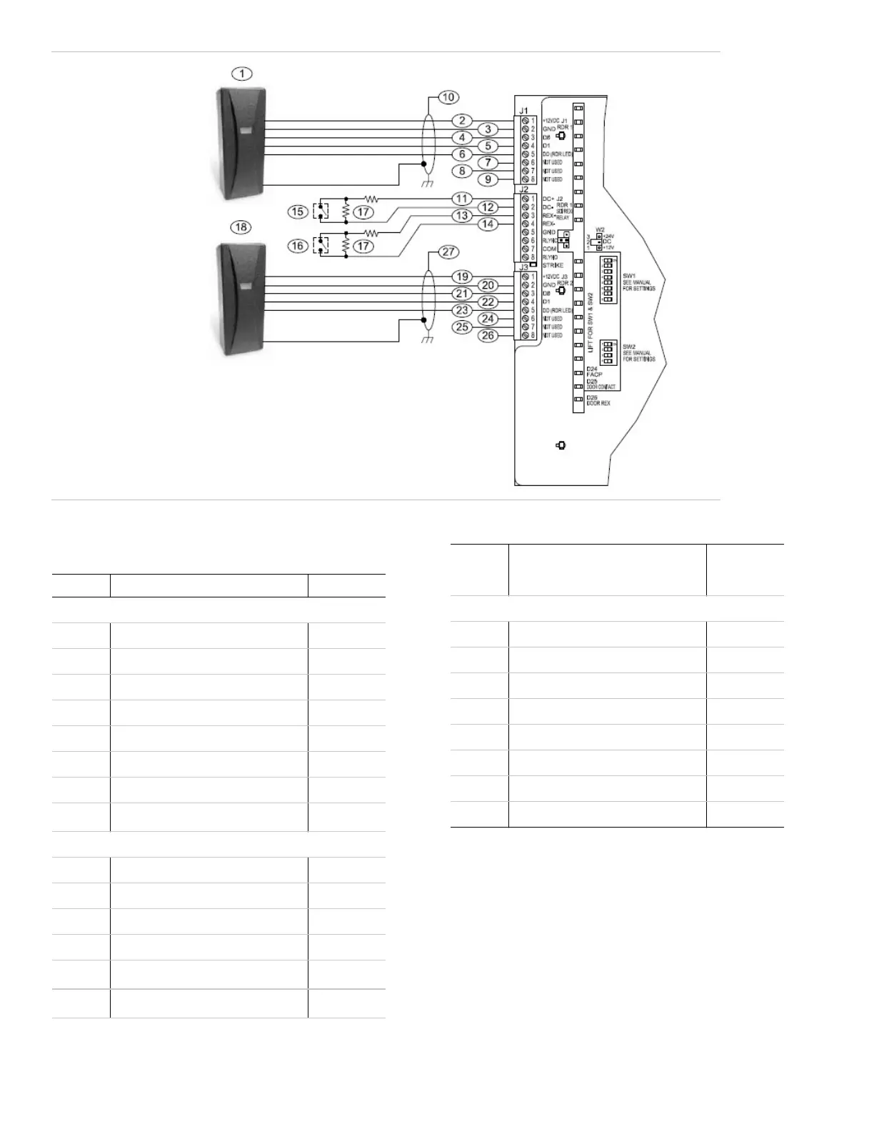
The following table lists the items shown in Figure 10.
Callout Description Wire Color
Connector J1
1 Reader 1 (access)
2 +12 VDC Red
3 Ground (0V) Black
4 Reader Data 0 Green
5 Reader Data 1 White
6 Door DO (green LED) Orange
7—9 Not used
10
Drain wire (cable shield)
[1]
Connector J2
11 Door DI (DC+)
12 Door DI Return (DC-)
13 Exit DI (REX+)
14 Exit DI Return (REX-)
15
Door Contact
[2]
16
REX
[2]
17
1K EOL resistors typical
[3]
Connector J3
18 Reader 2 (egress)
19 +12 VDC Red
20 Ground (0V) Black
21 Reader Data 0 Green
22 Reader Data 1 White
23 Door DO; green LED Orange
24—26 Not used
27 Drain wire (cable shield). See footnote 1
1. Use 20 AWG shielded cable and terminate drain wire
(cable shield) at enclosure (see Figure 3 on page 4).
Use plenum-rated cable if cable will be run above a
false ceiling in the air circulation space.
2. Door or Exit DIs Normally Open or Closed.
3. Include resistors for Wiegand Four-State interface.
For Wiegand Two-State interface, omit resistors.
Callout Description Wire Color
Figure 10: Wiegand Wiring
 Loading...