Chapter 1: Installation
28 CDC4 Door Controller Installation and Programming Manual
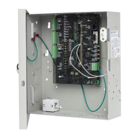
Figure 16: Connecting a smart card reader to the one of the buses
Shield: Connect to earth terminal
On the RS485 bus 1 and bus 2 interfaces, the +12 terminal is able to provide
+12 V to RASs or other remote devices.
Note: Devices connected to the buses and powered by the door controller must
comply with “Output fusing and user current draw” on page 38.
To prevent failures, false alarms and hazards, all wires inside the enclosure
should be insulated up to the point of contact. Typically less than 2 mm of bare
conductor should be exposed outside of the screw terminal blocks and all
conductor strands bound by the crew.
Damaged insulation, poor workmanship and other observed faults must be
corrected as soon as possible.
Bus termination
All Advisor Advanced devices (including the panel) use a 470 Ω bus termination
resistor where required. Bus termination resistors are used to set the impedance
of the data bus to around 220 Ω in order to minimise noise. The termination
resistor may be external or on-board (devices with an on-board resistor use a link
to set the bus termination to On).
An Advisor Advanced bus should have only two devices with the bus termination
set to On (or the bus termination resistor fitted):
• In a straight bus configuration, the TERM links are On at the Advisor
Advanced panel and the most distant device.
• In a star bus configuration, the TERM links are On at the two devices that are
the furthest apart (and OFF at the Advisor Advanced panel).
In a completely connected (but powered down) system, you can check for correct
bus termination by measuring the resistance across the D+ and D− terminals:
• 0 Ω indicates a short circuit in the cabling
• 160 Ω or less indicates that too many devices are terminated
• 220 Ω is good
• 470 Ω or more indicates that not enough devices are terminated