SPECIAL INSTRUCTIONS
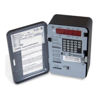
Opening the Logic Module To remove the metal logic
module cover, remove the screws on the back and lift off,
exposing the circuit board. Reverse steps to replace cover. The
following three procedures require cover removal.
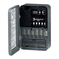
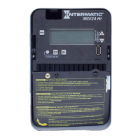
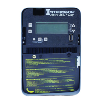
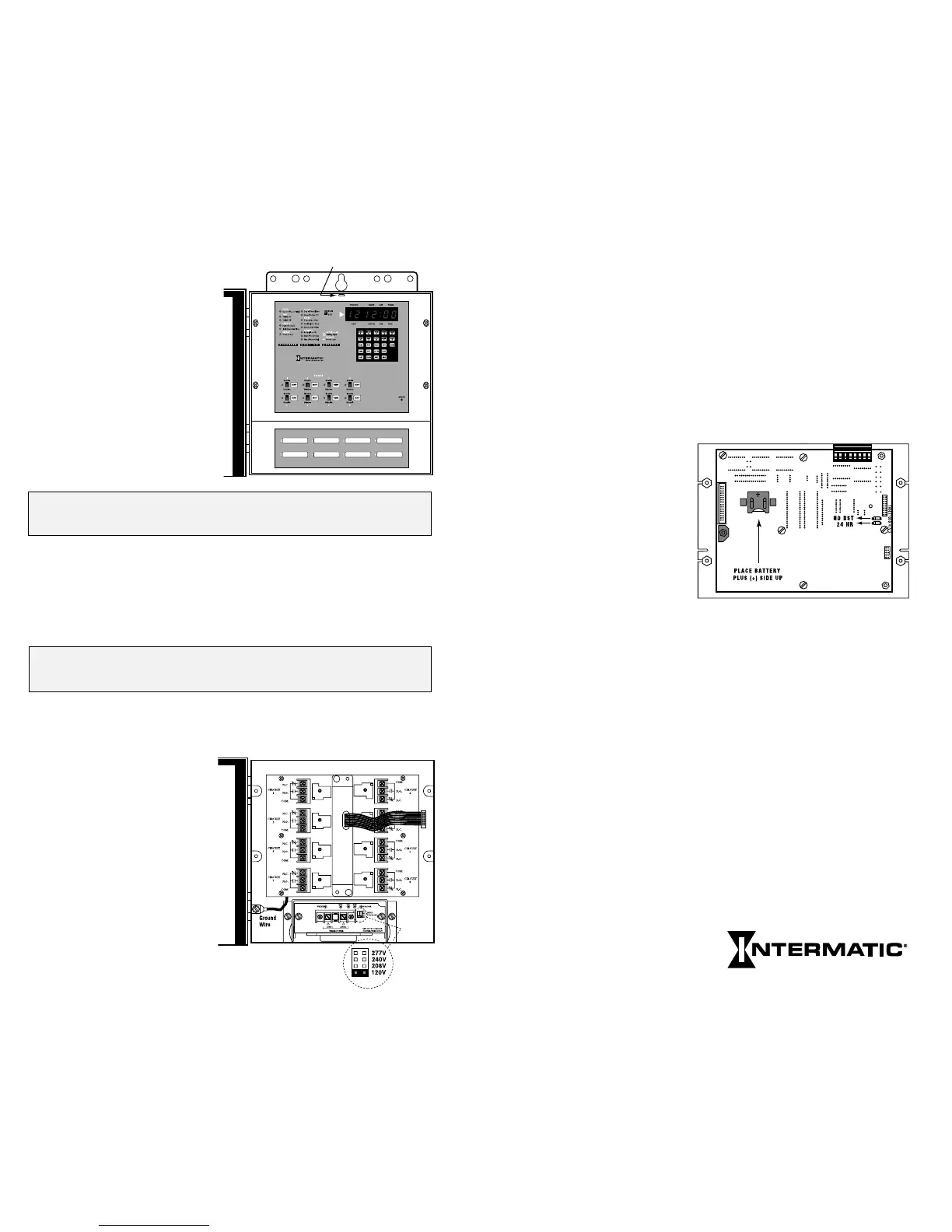
Converting to 24 Hour Display Mode The time switch is
shipped with 12 hr. AM/PM timekeeping; 24 hr. is available by
removing the jumper from the pin connector on the circuit
board. The jumper(s) may be stored for later use by reinstalling
on the outer pins only.
Daylight Saving Time
Override Override the
automatic DST adjustment
(in Arizona, Hawaii and
parts of Indiana) by
removing the jumper
on the circuit board.
Battery Replacement
The 8 yr. battery is located on the back of the circuit board under
the metal battery terminal clips. Replace with Panasonic or
Rayovac BR2325 (or equivalent).
Load Control Wiring With the logic module removed you
have access to the load control relays. Note all relays are identified
with circuit numbers 1–8 or 1–16. Each relay is also identified
with relay ladder diagrams for the common (COM), normally
open (N.O.) and normally closed (N.C.) connections.
NOTE: Contacts are isolated to enable switching loads of a
voltage different than the timer power voltage. You may need to
connect power to the common (COM) terminals. Add jumpers
as required. Do not mix solid and stranded wires under the
same terminal.
29
Next Generation
SPECIAL INSTRUCTIONS
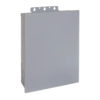
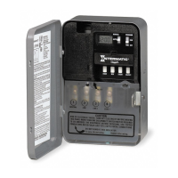
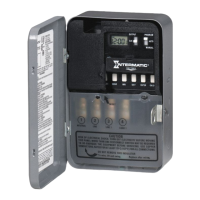
Enclosure Mounting
Follow the instructions
included with the 2
mounting brackets. They
have several holes (3 are
slotted) for securing the
enclosure. Mount using
suitable hardware. For ease
of installation the cover can
be removed by lifting
upward off the hinges.
WARNING: Disconnect all power at the service panel before
removing the logic module.
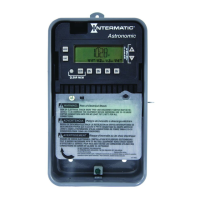
Removing Logic Module (required for wiring). Remove the 4
Philips Head screws and set them aside for reinstallation. Using a
flat-bladed screwdriver in the slot at the top of the logic module,
gently pull it away from the enclosure.
STOP: Disconnect cable from rear of logic module by pulling
straight back on the connector pull tab.
Changing Power Input Voltage–Multi-volt Models
ET70815CR and ET71615CR
These models can be
powered by any industry
standard 50–60Hz AC
voltage, 120 to 277 V. To
change from the 120VAC
factory setting, locate the
voltage selector jumper and
insert over the pair marked
with the desired voltage
(208, 240, or 277 VAC).
Slot for removal
28
24 HOUR MODE
DST OVERRIDE
BATTERY REPLACEMENT