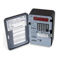
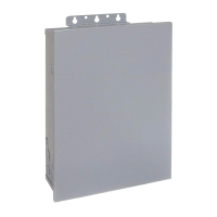
5. Place the enclosure in the desired location, position at eye level, and provide space for the enclosure door to swing open fully.
6. Drill the holes and then clean out each hole.
7. Insert plastic anchors into the holes, if needed.
IMPORTANT: If you are bringing power wires and wires for connecting applications through the back of the enclosure,
connect the wires before mounting the enclosure. Refer to the wiring diagrams in this manual.
8. Insert the top screw into the top hole and tighten. Hang enclosure.
9. Insert the remaining screws into the other holes and tighten.
10. Replace the time switch in the enclosure.
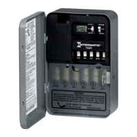
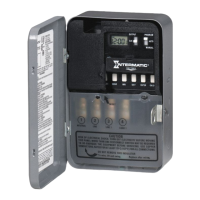
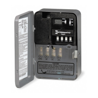
11. Remove and retain the screw that secures the plastic insulator.
12. Lift the left side of the plastic insulator off the retaining post and pivot it away to expose the terminal strip.
NOTE: Do not remove the insulator.
13. Strip the supply and load wires to 1/2”. Use AWG#14-#8 copper 105º conductors only. Torque to 15.6 lbf-in.
14. Connect the wires to the proper terminals on the time switch connector and tighten the screws firmly.
See wire diagrams.
15. Connect ground wire to grounding terminal at the bottom of the enclosure.
NOTE: Make sure no wire insulation is caught in the terminal.
16. Return the insulator to its original position and replace the screw.
17. Close the enclosure door.
18. Apply power to the time switch.
8.6
[219]
9.6
[243]
3.3
[83]
5.7
[145]
3.6
91
1/2 inch
Input and Output voltage are the same
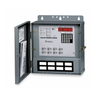
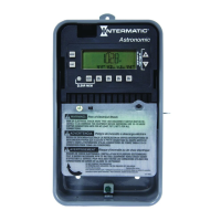
There are many different ways to set the relays on the ET8415CR
Time Switch. The four relays can be used individually or in pairs
of two. Refer to the table below for a complete list of ways to set
the relays and the illustrations for some of the common wiring
installations.
IND/IND SIM/IND PUL/IND
IND/SIM SIM/SIM PUL/SIM
IND/PUL SIM/PUL PUL/PUL
Note* IND = Independent SIM = Simultaneous PUL = Pulse
for both sets of contacts
.
For both sets of contacts
Each ON event for Circuit
and Each OFF event will Open Contactor
/208/240/277 VAC
VDC Input
.