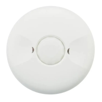
Low Voltage Occupancy Sensor
Input: +24VDC
Model#:
For Indoor Use Only
IOS-CMP-LV
DESCRIPTION:
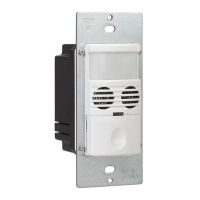
The IOS-CMP-LV 360° Passive Infrared (PIR) Low Voltage Occupancy Sensors control lighting systems
based on occupancy and ambient light levels. When movement is detected, the sensor turns the lights
ON. If no movement is detected for a user-specified or Autoset time of 15 seconds to 30 minutes, the
lights are turned OFF. The occupancy sensor provides a 360° coverage pattern, up to 1200 square feet.
MOUNTING THE SENSOR
NOTE: A junction box and Phillips screwdriver are needed to complete this procedure.
1. Make sure power is turned off at the main disconnect.
2. Remove the screws on the occupancy sensor cover and remove the cover from the sensor.
3. Observe these guidelines when mounting the sensor:
• The occupancy coverage area may be more or less than the sensing distances shown in Figure 1
due to potential coverage area obstacles, such as furniture or partitions.
• Place the sensor 4 to 6 feet away from air supply ducts to prevent false activations.
• If you mount the sensor outside of 8 to 11 feet from the floor, it affects the coverage pattern.
• Decreasing the mounting height decreases the sensor range and increases the sensitivity to
smaller motions. Mounting the sensor at heights more than 12 to 14 feet reduces sensitivity
• Each occupant should be able to clearly view the sensor to guarantee no obstruction in the area
• Avoid placing the sensor directly in line with an open door through which it has a clear view out.
This may cause the sensor to detect people walking by the door.
• To obtain complete coverage in large areas, install multiple sensors to create an overlap with each
adjacent sensor’s coverage area.
4. Punch knockout on the junction box and insert the IOS-PP24 power pack nipple into the knockout.
5. Pull the low voltage wires from the power pack into the junction box, through the conduit knockout.
6. Connect the low voltage wires from the power pack to the appropriate terminals on the occupancy
sensor. See table below for wire designations. Refer to FIgure 2.
Wire from power pack To Terminal on Occupancy Sensor
Red wire (+24 VDC) +24 VDC terminal
Black wire (Common) Common terminal
Blue wire Control Out terminal
IOS-CMP-LV INSTALLATION
1. If you want to connect multiple single loads for the sensor to control, connect the blue wire from the
power pack to the Control Out terminals on the sensor.
2. If you want to add a manual switch to the above application, connect a wire from one side of the
switch to the common terminal on sensor and connect another wire from the other side of the switch
to the Manual ON terminal on sensor.
3. Loosen the mounting screws attached to the junction box.
4. Align the sensor in the junction box so that the mounting screws in the box match the keyholes on
the sensor’s rear housing.
5. Push the sensor into the junction box and align the mounting screws on the junction box with the
keyhole slots on the sensor so that the screws are seated in the keyhole slots. Tighten mounting
screws.
ADJUST THE LIGHT LEVEL
The Light Level feature enables the user to adjust the level of light needed to be detected before
the sensor turns lighting ON. Remove the cover from the sensor and adjust the lighting from
the light level dial on the sensor (see Figure 5). You can set the dial anywhere between + or – to
obtain the optimal brightness configuration for the room (see Figure 3).
SENSOR ADJUSTMENT
Follow this procedure to verify the sensor coverage and customize the settings.
1. Remove the screws on the front cover and remove the cover.
2. Make sure all the furniture in the sensing area is installed, the lighting circuits are turned on and the
HVAC systems are in the Override position.
3. If there is a V AV system, set it to the highest airflow.
360˚ Passive Infrared
Low Voltage Occupancy Sensor
With Light Level Feature
MODEL: IOS-CMP-LV
Specifications:
Voltage - 24 VDC
Current Consumption - 9mA
Power Supply - IOS-PP24 Power Packs
Adjustable Light Level - 10FC-150FC
Adjustable Time Delay - 15 sec.-30 min (DIP switch)
Walk-Through Mode - 3 minutes if no activity after 30 sec.
Test Mode - 15 sec. upon initial power-up or DIP switch reset
PIR Coverage:
Sensitivity Adjustment - Automatic or Low (DIP switch)
Coverage - Up to 1200 ft
2
Figure 3
Figure 2
Figure 4
Figure 5
IOS-CMP-LV
terminals
Wiring
Common
+24VDC
Manual ON
Low Voltage Occupancy Sensor
Input: +24VDC
Model#:
For Indoor Use Only
IOS-CMP-LV
Control Out
Common
+24VDC
Manual ON
Control Out
- +
- +
- +
- +
- +
- +
Risk of Fire, Electrical Shock or Personal Injury
• Turn OFF power at circuit breaker or fuse and test that the power is OFF before wiring.
• To be installed and/or used in accordance with appropriate electrical codes and regulations.
• If you are not sure about any part of these instructions, consult a qualified electrician.
• Use this device only with copper or copper clad wire.
• INDOOR USE ONLY
WARNING
44 ft
13.4m
8 ft
tf 22tf 22 tf 31tf 31 7 ft 7 ft3 ft 0 3 ft
Typical
desk-top
level
Figure 1
J-Box Mount
Front Cover
Rear Housing
Wire
Screws
4" Octagonal
box 2-1/2"
Deep mounting
Drop
Ceiling
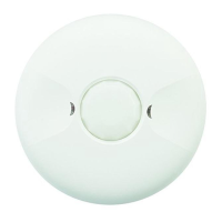
PIR lens
PIR Activity LED(Red)
Light level Adjustment
Double gang mudring
mounting holes
DIP switches
Keyhole slots
Keyhole slots(for mounting to
4" octagonal box)
Load LED(Green)
Buzzer
(for mounting to 4" octagonal box)
INSTALLATION AND CONFIGURATION INSTRUCTIONS