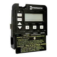
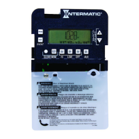
Display Definitions
Cool Down (Fireman Switch) Runtime Display
The following example illustrates how the display will
look when the cool down feature is activated. In this
example, the cool down time was set for 5 minutes, and
is in the process of counting down to zero, showing
minutes and seconds.
The AUX1 indicator is blinking indicating the cool
down feature is activated for circuit #1. When the
count down display reaches zero, the actuated circuits
(#1 or #2) depending on mode (2 or 4), will open
and the display will change back to the time of day.
You can override the cool down feature by simply
pressing and releasing the ON/OFF key associated
with circuit #1. This will end the cool down cycle, and
immediately turn off circuit #1.
32
9
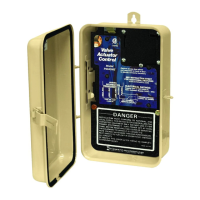
STEP #3
ROUTE ACCESSORY WIRES AND
CONNECTORS INTO ENCLOSURE AND
CONNECT TO THEIR PROPER LOCATIONS
Installation Procedure
1 Push the Fireman Switch wires and/or the Freeze
Sensor Cable through the installed Shutter
Bushing and into the control center. Connect these
accessories to the back of the multipurpose control
mechanism (See Figure #1 for connector locations).
Control Center
Freeze Sensor Cable
Shutter Bushing
Fireman Switch Wires
Figure #3