EasyManua.ls Logo

Intermatic P1353ME User Manual

Intermatic P1353ME
21 pages
To Next Page IconTo Next Page
Page #1 background imageLoading...
Page #1 background image
INSTRUCTION MANUAL
INTERMATIC
MULTIPURPOSE CONTROL
MECHANISM MODEL: P1353ME
12345
67
ATTENTION
READ CAREFULLY BEFORE ATTEMPTING TO
INSTALL YOUR INTERMATIC MULTIFUNCTION
CONTROL SWITCH. FAILURE TO COMPLY WITH
INSTRUCTIONS COULD RESULT IN PERSONAL
INJURY AND/OR PROPERTY DAMAGE! RETAIN
FOR FUTURE REFERENCE.
158--01654
Question and Answer IconNeed help?

Do you have a question about the Intermatic P1353ME and is the answer not in the manual?

Intermatic P1353ME Specifications

General IconGeneral
ModelP1353ME
CategoryController
Voltage120V
Amperage15A
DisplayLCD
Battery BackupYes
Number of Outlets1
Mounting TypeWall Mount

Summary

ATTENTION

1-Year Limited Hardware Warranty

INTRODUCTION

WARNINGS AND GENERAL SAFETY INFORMATION

Clearing all scheduled ON/OFF Events Quickly

INSTALLATION TIPS & USEFUL INFORMATION

Viewing the Software Revision Level

Procedure to view the internal programming revision level for service or compatibility checks.

STEP #1 IDENTIFY LOW VOLTAGE ACCESSORY CONNECTIONS AND SET PROPER VOLTAGE SELECTION

Source Voltage Selector Jumper

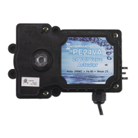
Instructions for setting the voltage selector jumper for proper input voltage to avoid damage.

Special Features

Setting The Countdown Timer

Procedure to set a temporary runtime for a circuit, overriding scheduled events.

STEP #2 INSTALLING THE SHUTTER BUSHING

Display Definitions

Cleaner Pump Display

Defines the icon and behavior for the cleaner pump output on the control display.

Freeze Control Display

Illustrates how the display looks when freeze protection is activated.

STEP #3 ROUTE ACCESSORY WIRES AND CONNECTORS INTO ENCLOSURE AND CONNECT TO THEIR PROPER LOCATIONS

STEP #4 SNAP THE MULTIPURPOSE CONTROL INTO THE INTERMATIC PANEL

STEP #10 Setting Freeze Protection

STEP #9 Setting The Cool Down Time (Fireman Switch)

STEP #5 CUT & INSTALL TUBING OVER THE LOW VOLTAGE ACCESSORY WIRES AND/OR CORDS

AN OVERVIEW OF THE MULTIPURPOSE CONTROL PANEL

Control Panel Interface Elements

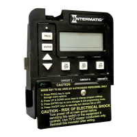
Description of the Mode, Program, Enter buttons, and the main display.

STEP #8 Setting On/Off Times for Each Circuit

Programming Controls and Circuit Connections

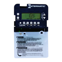
Explanation of arrow buttons, ON/OFF buttons, circuit terminals, and timer power connections.

STEP #7 Setting The Time

Time Setting Interface Controls

Guide to using the Program Key, Up/Down Arrows, and Display for setting the time.

MODES OF OPERATION

Setting The Mode

Procedure to select the appropriate mode for equipment configuration.

STEP #6 MULTIPURPOSE CONTROL RATINGS, WIRING AND SETTING THE MODE

Control Ratings and Circuit Specifications

Details on control voltage, power consumption, contact ratings, and memory retention.

Circuit Wiring Terminals

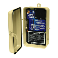
Description of the six terminals for wiring equipment load lines and source voltage.

IMPORTANT NOTE CONCERNING SETTING THE ON/OFF TIMES FOR EACH MODE

Mode 6 - (Aux1, Aux2, Aux3) Operation

Details the independent operation of three circuits for generic loads and fireman switch functionality.

Mode 3 (Filter Pump, Aux2, Cleaner Pump) Operation

Mode 4 (Pump High, Pump Low, Cleaner Pump) Operation

Defining & Wiring Each Mode

Mode 1 - (Aux1, Aux2, Aux3) Definition and Wiring

Details the independent operation of three generic circuits with their wiring diagrams.

Mode 4 (Pump High, Pump Low, Cleaner Pump) Wiring

Wiring diagram for a two-speed pump and cleaner pump configuration.

Mode 2 - (Pump High, Pump Low, Aux3) Description and Wiring

Mode 3 (Pump, Aux2, Cleaner Pump) Description and Wiring

INTERMATIC® POOL / SPA EQUIPMENT CONTROL ACCESSORIES SAFETY SHIELD KIT

Related product manuals