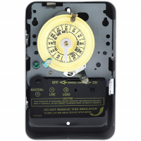
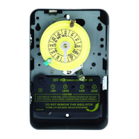
Trippers are “IN”
Indicates
Output is OFF
GREEN LED – OFF
Trippers are “OUT”
Indicates
Output is ON
GREEN LED – ON
GM40 TROUBLESHOOTING GUIDE
GM40 CONTACT TERMINALS TRANSITION
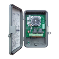
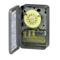
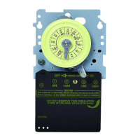
White arrow on timer module points to current time.
ORANGE
POWER
GREEN
STATUS
S
1 S
etting:
120V:
A
LL ON
200V - 240V: 1 & 3 ON
277V: A
LL
O
FF
S1
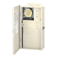
GM40 MOUNTING INTO INTERMATIC ENCLOSURE
PROBLEM: LOAD (Lights/Pumps/Motor, etc.) does not turn ON
1. Check AMBER Power LED, if ON it indicates power is applied to GM40.
2. Verify correct input voltage DIP switch setting (refer to page 1).
3. Check voltage across terminals L1 and L2/N with Multi-meter.
4. Slide manual override switch (locate on right side of timer module) up. The
GREEN LED should illuminate indicating that the output should be ON.
5. Check wiring (refer to page 3).
PROBLEM: LOAD (Lights/Pumps/Motor, etc.)
does not turn OFF
1. Verify manual override switch is set to the middle
position.
2. Verify correct programming dial (refer to page 2).
3. Slide manual override switch (located on right side of timer module) down.
The GREEN LED should turn OFF indicating that the output should be OFF.
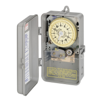
Mounting GM40 Mechanism into existing Intermatic
Metal Enclosure
The GM40 Series printed circuit board assembly will fit
into all Intermatic enclosures except the T7000 and
T5000 Series. Install GM40-M into Intermatic enclosure
in the same manner as the Intermatic mechanism was
previously installed.
AMBER LED
Illuminated when power is
applied to the GM40
GREEN LED
Illuminated when GM40
output is ON
TIMER
T
COM2NO2NC2
COM
NO
NCL2/NL1
TIMER
T
COM2NO2NC2
COM
NO
NCL2/N
L1
Status of Contacts
Note: Power must be applied across terminals L1 and L2/N in order for contacts to transition.
Status of Contacts
Intermatic, Inc.
7777 Winn Road
Spring Grove, IL 60081
www.intermatic.com