11
Wiring for Power and Transducer
Connectors
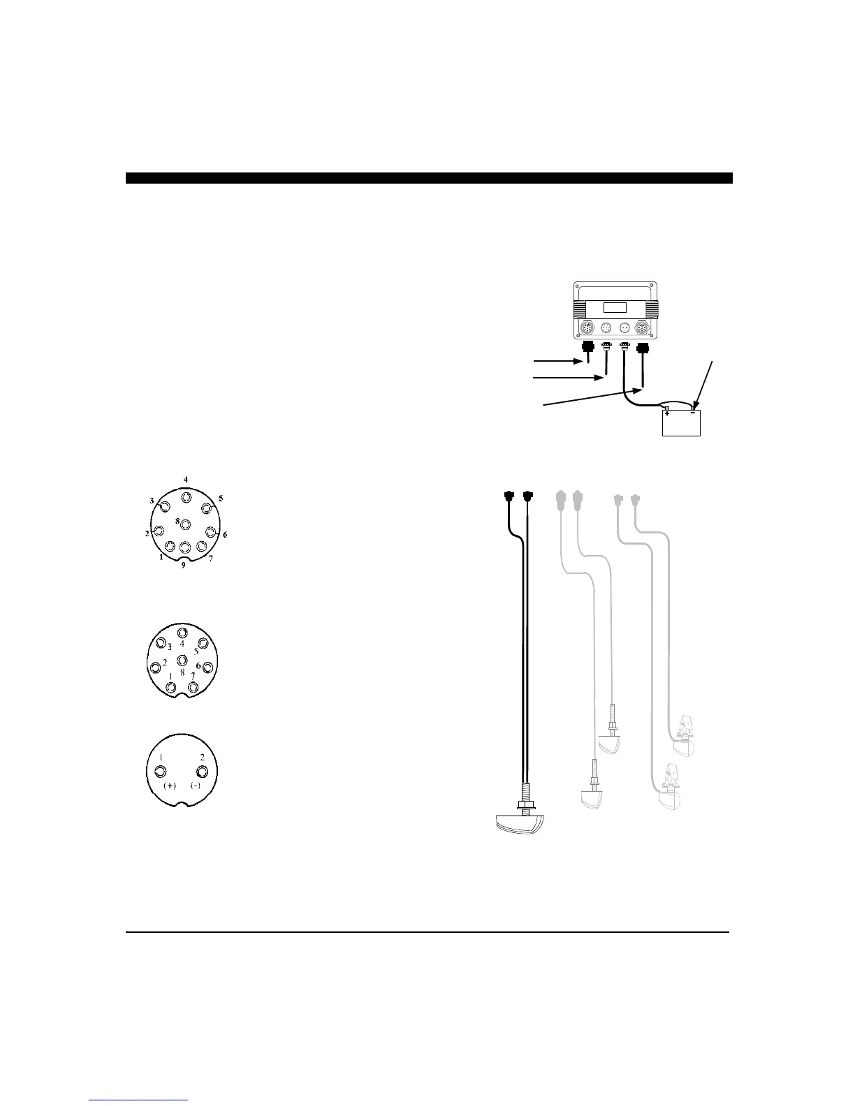
The correct pin-out wiring sequences for the power and
transducer connectors are shown at below. DO NOT
SHORTEN THE TRANSDUCER CABLES. If
transducer cables longer than the 30’ length supplied with
your unit is needed, please contact your Interphase
dealer. 30-foot scanning sonar transducer extension
cables are available. (P/N # 04-0014-008)
DANGER: Removal of any connector, disassembly of
transducer, shortening of any cable or use of any cable
other than that supplied by Interphase will void your
warranty. NO EXCEPTIONS.
Cable Connectors (view from front of female
plug)
Transducers:
1 White 1st element
2 Brown 2nd element
3 Orange 3rd element
4 Yellow 4th element
5 Green 5th element
6 Blue 6th element
7 Violet 7th element
8 Gray 8th element
9 Shield Ground/Return
NMEA & SPEED/TEMP Input
1 Speed Data
2 +5VDC
3 NMEA Data
4 N/C
5 NMEA Return
6 + Temp
7 - Temp
8 Shield/Ground
Power Connector
1 +12 vdc (red)
2 - Ground (black)
SINGLE THRU-HULL
TWO TRANSOM MOUNTS
TWO THRU-HULL'S
(T1-I200-032)
(T1-I200-026 - vertical)
(T1-I200-029 - horizontal)
(T1-0200-025 - vertical)
(T1-0200-028 - horizontal)
12 VDC
Battery
Power and Transducer
Connections
vertical transducer cable
speed/temp & NMEA
horizontal transducer cable
Transducer Configurations