Pub. No. 18-HE122D1-1-EN Numbers in [brackets] are for 50 Hz international systems. 13
Installer’s Guide
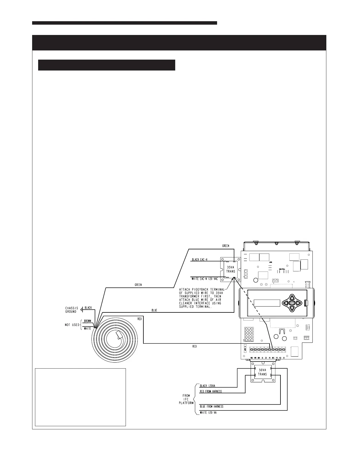
ELECTRICAL CONNECTIONS TO A COMMUNICATING FURNACE IN 24 V MODE
HAZARDOUS VOLTAGE! DISCONNECT ALL ELECTRIC
POWER, INCLUDING REMOTE DISCONNECTS BEFORE
SERVICING. FOLLOW PROPER LOCKOUT/TAGOUT
PROCEDURES TO ENSURE THE POWER CAN NOT
BE INADVERTENTLY ENERGIZED. FAILURE TO
DISCONNECT POWER BEFORE SERVICING COULD
RESULT IN DEATH OR SERIOUS INJURY.
PROCEDURE:
1. Remove electrical power going into the furnace.
2. Removeblowerdoortoup-owordown-owfurnace.
3. Remove the two screws that secure the IFC platform to the under-
sideoftheblowerdeckonanup-owfurnaceorthe3screwsthat
securetheIFCplatformtothetoppanelonadown-owfurnace.
4. Carefully remove the IFC platform from the furnace.
5. Onboththeup-owanddown-owfurnaces,mountthe50VA
transformer supplied in the packaging with the air cleaner onto the
bottom of the IFC platform. Screws and pilot holes are provided.
Seegure.
6. Removewiringfromexisting35VAtransformerandreconnecttothe
50VAtransformer.Notethepolarityofthewiresandreconnectto
the appropriate terminals. See diagram
7. RemovetheEAC-H115VACandEAC-Nwires(whiteandblack)
out of the junction box and pull them through the grommet in the
blowerdeck.Attachtwosupplied¼”insulatedfemalequickconnect
terminals by stripping the wires and crimping the terminals onto
thewires.Attachthesewirestothe115Vterminalsofthe35VA
transformer as shown in the diagram.
8. Remove the wiring harness supplied with the air cleaner from the
packaging.Attachasupplied3/16”insulatedfemalequickconnect
terminal to the blue wire and the green wire.
9. Attachthebluewirefromtheaircleanerwiringharnesstotheopen
tabonthepiggybackterminalsuppliedintheBAYACCECOMM101.
Attachpiggybackterminaltothe35VAtransformerterminal“C”
(Common).
10. Insertthe12”bluestrippedwireundertheterminalstripscrew
marked“B/C”ontheIFCcontrolboard.Iftheapplicationalsoin-
cludesanoutdoorunit(communicatingornon-communicating),the
B/Cterminalwillrequire3wiresconnected.Forthisconnection,
rather than connecting the three wires to the low voltage terminal
striponthefurnaceIFC,createapigtailusingashortlengthof
thermostatwireandawirenut(eldsupplied)toattachtotheB/C
terminal.
11. Connect the green wire from the air cleaner wiring harness to the
24Vterminalonthe35VAtransformerlabeled“RD”.Seediagram.
12. Insert the red stripped wire from the air cleaner wiring harness un-
dertheIFCcontrolboardterminalscrewmarked“R”.Seediagram.
13. Attachtheblackstrippedwirefromtheaircleanerwiringharness
directly to ground with a screw on the furnace chassis. See dia-
gram.
14. Oncealloftheconnectionshavebeencompleted,remounttheIFC
control platform into the furnace.
15. Secure any loose wiring with wire ties.
16. ThebrownandwhitewiresfromtheEACwiringharnessare
unused in this application and should be insulated. See diagram.
17. Replace the furnace door.
18. Reconnect electrical power to the furnace.
19. Check both furnace and air cleaner operation per the furnace and
air cleaner installer guides.
BILL OF MATERIALS:
QTY:2 Screw
QTY:1 4"InsulatedCopperWire–
Blue(18AWG,AWM)
QTY:2 1/4”InsulatedFemaleQuick
Connect Terminal
QTY:2 3/16"x0.020"InsulatedFemale
Quick Connect Terminal
QTY:1 3/16"x0.020"Receptacle&Tab
These instructions and listed parts are included in KIT# BAYACCECOMM101