14 Numbers in [brackets] are for 50 Hz international systems. Pub. No. 18-HE122D1-1-EN
Installer’s Guide
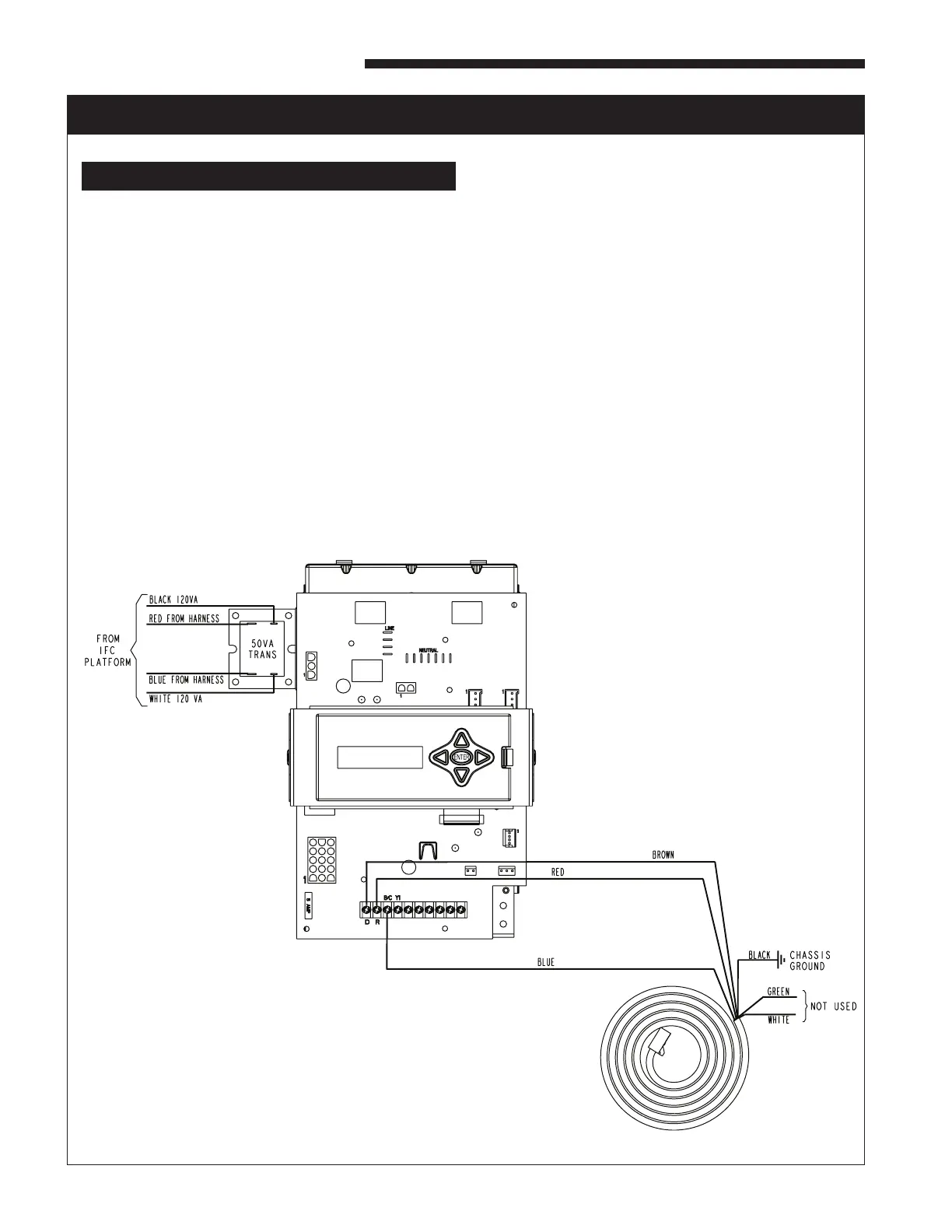
ELECTRICAL CONNECTIONS TO A COMMUNICATING SYSTEM FURNACE
HAZARDOUS VOLTAGE! DISCONNECT ALL ELECTRIC
POWER, INCLUDING REMOTE DISCONNECTS BEFORE
SERVICING. FOLLOW PROPER LOCKOUT/TAGOUT
PROCEDURES TO ENSURE THE POWER CAN NOT
BE INADVERTENTLY ENERGIZED. FAILURE TO
DISCONNECT POWER BEFORE SERVICING COULD
RESULT IN DEATH OR SERIOUS INJURY.
PROCEDURE:
1. Remove electrical power going into the furnace.
2. Openblowerdoortoupowordownowfurnace.
3. Disconnectallwiresonthe35VAtransformer.
4. Removethe35VAtransformerfromtheIFCplatform.
5. Mountthe50VAtransformersuppliedinthepackagingwiththe
aircleanerontotheIFCplatformwherethe35VAtransformerwas
previously located. Use the sheet metal screws supplied with the
aircleanertomountthe50VAtransformer.Reconnectthe115V
and24Vwiresthatwereconnectedtothe35VAtransformeronto
the50VAtransformer.
6. ConnectRedstrippedwireto"R"terminalonthefurnacecontrol
board.
7. ConnectBluestrippedwireto"B"terminalonthefurnacecontrol
board.
8. ConnectBrownstrippedwireto"D"terminalonthefurnacecontrol
board.
9. Attachtheblackstrippedwirefromtheaircleanerwiringharness
directly to ground with a screw in the chassis.
10. Thegreenandwhitewiresontheaircleaningwiringharnessare
unused in this application and should be insulated.
11. Replace door on furnace.
12. Reconnect electrical power to the furnace.
13. Check both furnace and air cleaner operation per the furnace and air
cleaner installer guides.