Do you have a question about the Intertek 51014 and is the answer not in the manual?
Lists all items included in the fan package, including the motor assembly and hardware.
Details all hardware components provided for fan assembly, such as screws and washers.
Specifies the necessary tools for assembly, like screwdrivers and pliers.
Diagram showing fan dimensions A, B, C, and D for reference during installation.
Explains the Downrod Mount and Angled Ceiling Mount options for installation.
Covers precautions like checking screws, not bending parts, and stopping fan before adjustments.
Ensures outlet box is securely attached to building structure for fan support.
Information regarding compliance with FCC and Industry Canada radio frequency regulations.
Warnings on shutting off power, blade clearance, and avoiding dimmer switches.
Turn off electrical power at the main fuse or circuit breaker before starting.
Install the mounting bracket to the outlet box using provided screws and washers.
Prepare the downrod by removing the clip and pin and loosening yoke set screws.
Feed wires and braided cable through the yoke cover, canopy, and downrod.
Insert downrod into yoke, reinstall pin/clip, and retighten set screws.
Seat downrod tab in mounting bracket slot to prevent rotation and ensure safety.
Install safety cable loop through outlet box and over ceiling brace for support.
Connect household supply wires to fan wires (Green, White, Black, Blue).
Align and rotate canopy onto mounting bracket screws, then secure with screws.
Attach blades to motor assembly using blade screws, washers, and screw caps.
Install bulbs into the light kit sockets, allowing them to cool first.
Attach glass bowl to light kit by loosening and retightening thumbscrews.
Attach pull chain extensions and turn on power to complete installation.
Use the reverse switch (left for cool, right for warm) to control airflow direction.
Control fan speed using the fan pull chain (4 positions) and light using the light pull chain.
Check power, circuit breakers, wire connections, and reverse switch position.
Ensure screws are snug, wires are not rattling, and avoid variable speed controls.
Verify bracket security, blade tightness, and use balancing kit if needed.
Check connectors, blue wire connection, bulb condition, and total wattage.
Covers fan motor for life, parts for one year; excludes glass and finishes.
Excludes damage from misuse, improper installation; non-licensed service invalidates.
Original purchaser must report defects within first year; replacement or repair offered.
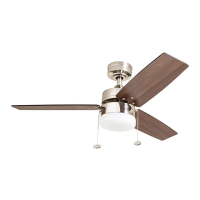
This document is an owner's manual for a 42-inch ceiling fan, specifically models #51014, #51015, and #51478. It provides detailed instructions for assembly, operation, troubleshooting, and warranty information.
The device is a 42-inch ceiling fan designed to provide air circulation and illumination in a room. It features a reversible motor for seasonal use, allowing for downward airflow in warmer weather to create a wind chill effect and upward airflow in cooler weather to help move stagnant, hot air off the ceiling area. The fan also includes a light kit for ambient lighting.
The manual emphasizes several critical safety precautions:
The product comes with a Limited Lifetime Warranty. The fan motor is warranted to be free from defects in workmanship and material for the life of the product. Other ceiling fan parts (excluding the motor and parts made with glass) are warranted for one year from the date of purchase. The warranty covers repair or replacement of defective parts but excludes costs of removal and reinstallation, damage from ordinary wear and tear, accident, misuse, improper installation, or service by non-licensed electricians. The warranty is void if the original purchaser ceases to own the fan.