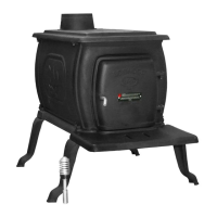
-10-
Operation Of The Heater
1. Burn wood or wood products only. The wood should be well
seasons prior to use for maximum efciency.
2. Provide air into the room for combustion.
3. Do Not touch the heater after ring until it has cooled.
4. Do Not use a grate or elevate re, build re directly on hearth.
The fuel feed door must remain closed during operation.
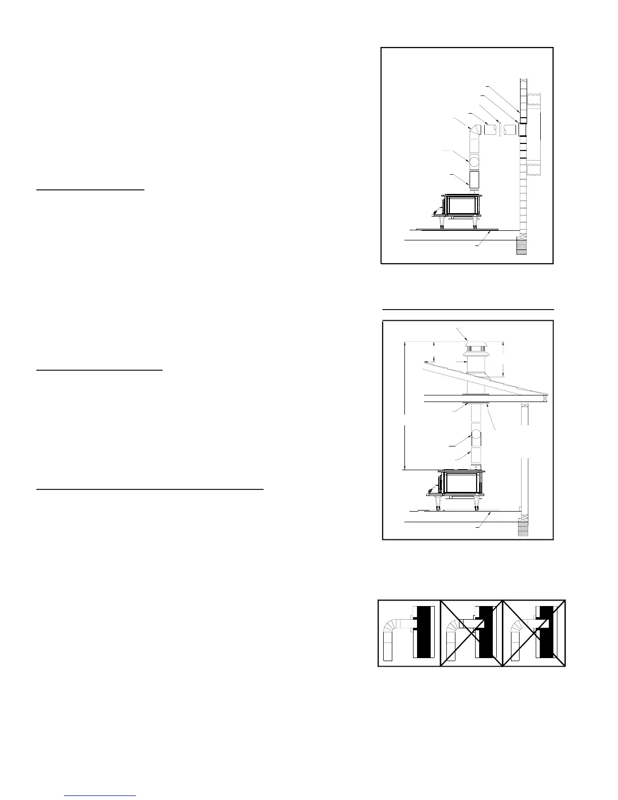
Chimney Connection
MASONRY CHIMNEY
The masonry chimney must comply with UL, ULC codes. Before using
an existing masonry chimney, clean the chimney and inspect the ue
liner to be sure it is safe to use. Make repairs before attaching the
heater. See Page 3, Item 5. Look at Fig. 5. The connector pipe and
ttings you will need to connect directly to a masonry chimney are
shown. If the connector pipe must go through a combustible wall
before entering the masonry chimney, consult a qualied mason or
chimney dealer. The installation must conform to local re codes, and
NFPA 211(USA) or CAN/CSA-B365-M91(CANADA). Do not connect
this heater into the same chimney ue as the replace or ue from
another heater. The chimney used for a heater must not be used to
ventilate the cellar or basement. If there is a clean out opening at the
base of the chimney, close it tightly.
UL/ULC LISTED CHIMNEY
Carefully follow chimney manufacturer's instructions. Use only listed
type UL 103 HT or ULC 629, 6-in diameter black or blued chimney
connector, minimum 24 gauge steel. If your chimney starts at the
ceiling (Fig. 6), you will need enough 6" pipe to reach the ceiling.
The top of the chimney must be at least 3 feet above the roof and
be at least 2 feet higher than any point of the roof within 10 feet.
(Fig 6). Use double or triple wall pipe for the exterior portion of the
chimney.
RULES FOR CONNECTOR PIPE INSTALLATION
1. Crimped end of the pipe must be installed toward the heater.
The pipe should slide into the ue collar. The pipe should be rmly
attached to the ue collar with 3 screws and sealed with furnace
cement.
2. Slope any horizontal pipe upward toward the chimney at least
1/4 inch for each foot of horizontal run. Horizontal section must
be a minimum of 24" from stove.
3. You must have at least 18" inches clearance between any
horizontal piping and the ceiling.
4. The pipe cannot extend into the chimney ue.(Fig. 7)
5. Seal each connector pipe joint with furnace cement. Also, seal
the pipe at the chimney. Seal the inside with high temperature
silicone and the outside with high temperature tape.
6. Use 3 sheet metal screws at each joint to make the piping rigid.
7. It is recommended that no more than two (2) 90 degree bends
be used in the stove pipe installation as more than two (2) may
decrease the amount of draw and possibly cause smoke spillage.
NOTE: The chimney connector shall not pass through an attic,
roof space, oor, ceiling, or similar concealed space. Where
passage through a wall or partition of combustible construction
is desired, the installation must conform with CAN/CSA - B365.
FIG. 5
ELBOW
COLLAR
THIMBLE
FLOOR PROTECTOR
FLUE CONNECTION-NON-COMBUSTIBLE WALL
PIPE
NONCOMBUSTIBLE WALL
PIPE
BAROMETRIC
DRAFT REGULATOR
FIG. 6
PIPE REDUCER
FLOOR PROTECTOR
3 FT. MIN.
2 FT. MIN
10 FT.
CHIMNEY CAP MANDATORY
11 FT. MINIMUM
FIG. 7
WRONG
FLUE CONNECTION-NON-COMBUSTIBLE WALL
PIPE
NONCOMBUSTIBLE WALL
PIPE
BAROMETRIC
DRAFT REGULATOR
BAROMETRIC
DRAFT REGULATOR
PIPE
NONCOMBUSTIBLE
CONSTRUCTION IN
ACCORDANCE WITH
NFPA 211
WRONG
RIGHT
FIG. 6
FIG. 5
ELBOW
COLLAR
THIMBLE
PIPE REDUCER
FLOOR PROTECTOR
FLOOR PROTECTOR
3 FT. MIN.
2 FT. MIN
10 FT.
CHIMNEY CAP MANDATORY
11 FT. MINIMUM
FIG. 7
WRONG
FLUE CONNECTION-NON-COMBUSTIBLE WALL
PIPE
NONCOMBUSTIBLE WALL
PIPE
BAROMETRIC
DRAFT REGULATOR
BAROMETRIC
DRAFT REGULATOR
PIPE
NONCOMBUSTIBLE
CONSTRUCTION IN
ACCORDANCE WITH
NFPA 211
 Loading...