MAINTENANCE
Page 2.3
04/02
Scope
1 This chapter details the removal and/or replacement procedures required for the following assemblies
and/or items. It is not intended to be a strict policy of maintenance but should be used as a guide only.
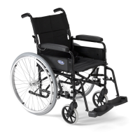
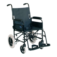
2 The assemblies covered (refer to Fig 2.0.1) are as follows:
Section Assembly Page
2.1 Backrest 2.6
2.2 Armrest 2.8
2.3 Rear wheels (12 1/2 inches) 2.10
2.4 Brake assembly 2.14
2.5 Removing and replacing a castor assembly 2.16
2.6 Adjustable footrest 2.18
2.7 Seat canvas 2.20
3 For the tools required refer to the list of tools detailed in paragraph 12. Any special tooling and/or torque
requirements will be referred to within the relevant text.
4 General engineering practices and safe working practices must be adhered to at all times.
5 For further information on the assemblies contained within this chapter, contact Customer Services,
INVACARE Ltd., (refer to address in chapter 1) quoting the following details:
5.1 Part Number
5.2 Description
5.3 Quantity required
6 For certain orders the following should also be quoted:
6.1 Serial or batch number
6.2 End user
7 For any ordering or spares procurement, contact INVACARE Ltd., (refer to address in Chapter 1) quoting
the details in paragraphs 5 and 6.
Inspection
8 In general, a weekly visual check will meet all the inspection requirements.
9 Ensure that the following are checked:
9.1 Fabric is undamaged and has no signs of sagging.
9.2 The footrest is correctly fitted.
9.3 Both armrests are securely fitted in place.
9.4 Brake mechanism operates freely and when locked, the chair does not move.
9.5 Footplates are undamaged and are correctly fitted.
9.6 Tyres are in good order and the wheels are not damaged.
9.7 If stabilisers are fitted, they are firmly locked in place.