12
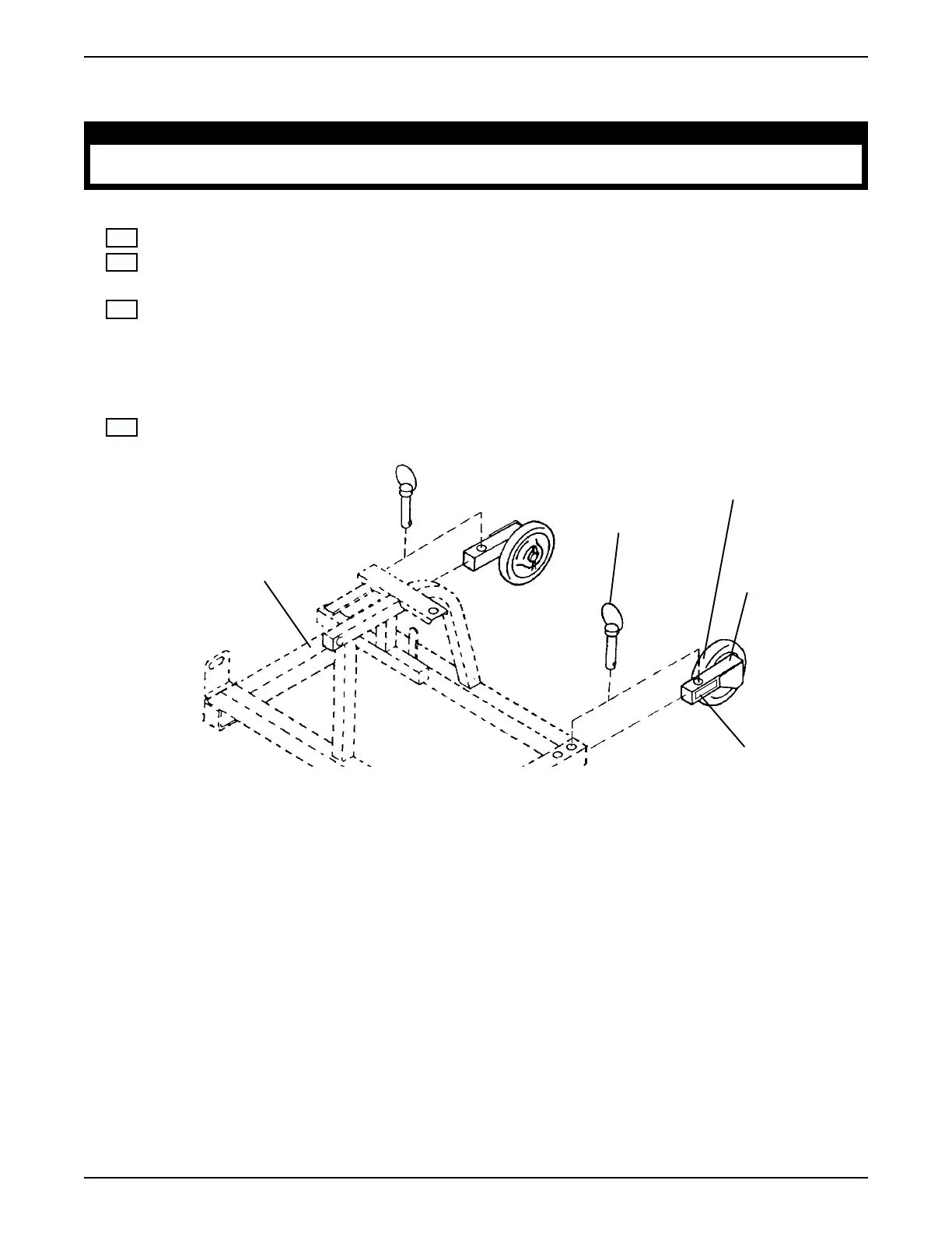
E. ANTI-TIPPER WHEEL ASSEMBLY INSTALLATION (FIGURE 14)
WARNING
DO NOT operate the scooter without the anti-tipper wheel assemblies installed. Anti-tipper wheel as-
semblies MUST be attached at all times - otherwise, injury or damage may occur.
Check Box When
Completed
1. Locate the two (2) anti-tipper wheel assemblies.
2. From the REAR of the scooter, remove the quick release pin on the LEFT side of the scooter sub-
frame assembly (FIGURE 14).
3. Slide the anti-tipper wheel assembly into the LEFT side of the sub-frame assembly and secure with
the quick release pin. Ensure the quick release pin is protruding through the bottom of the sub-frame
assembly (FIGURE 14).
NOTE: To check for proper installation, the anti-tipper wheel should be facing the inside of the scooter and
the warning label should face the outside of the scooter (FIGURE 14).
4. Repeat STEPS 2-3 for the RIGHT side anti-tipper wheel assembly.
FIGURE 14 - ANTI-TIPPER WHEEL INSTALLATION
Sub-Frame Assembly
Anti-Tipper
Wheel Assembly
Quick
Release
Pin
Wheel (Facing
Inside Of
Scooter)
Warning Label
(Facing Outside
Of Scooter)
ANTI-TIPPER WHEEL ASSEMBLY INSTALLATION
 Loading...