Page 30
Refrigerant Piping Connection
Safety Precautions
• All eld piping must be completed by a
licensed technician and must comply with
the local and national regulations.
• When the air conditioner is installed in a
small room, measures must be taken to
prevent the refrigerant concentration in
the room from exceeding the safety limit
in the event of refrigerant leakage. If the
refrigerant leaks and its concentration
exceeds its proper limit, hazards due to
lack of oxygen may result.
• When installing the refrigeration system,
ensure that air, dust, moisture or foreign
substances do not enter the refrigerant
circuit. Contamination in the system may
cause poor operating capacity, high
pressure in the refrigeration cycle,
explosion or injury.
• Ventilate the area immediately if there is
refrigerant leakage during the installation.
Leaked refrigerant gas is both toxic and
ammable. Ensure there is no refrigerant
leakage after completing the installation
work.
11
Refrigerant Piping Connection Instructions
• The branching pipe must be installed
horizontally. An angle of more than 10°
may cause malfunction.
• DO NOT install the connecting pipe until
both indoor and outdoor units have been
installed.
• Insulate both the gas and liquid piping to
prevent water leakage.
Step1: Cut pipes
When preparing refrigerant pipes, take extra
care to cut and are them properly. This will
ensure efcient operation and minimize the
need for future maintenance.
1.
Measure the distance between the indoor
and outdoor units.
2.
Using a pipe cutter, cut the pipe a little
longer than the measured distance.
DO NOT deform pipe while cutting. Be extra
careful not to damage, dent, or deform the
pipe while cutting. This will drastically reduce
the heating efciency of the unit.
1.Make sure that the pipe is cut at a perfect 90°
angle. Refer to Fig. 7.1 for examples of bad cuts
Oblique Rough Warped
90°
Fig. 11.1
Step 2: Remove burrs.
Burrs can affect the air-tight seal of refrigerant
piping connection. They must be completely
removed.
1. Hold the pipe at a downward angle to
prevent burrs from falling into the pipe.
2. Using a reamer or deburring tool, remove
all burrs from the cut section of the pipe.
Pipe
Reamer
Fig. 11.2
WARNING
CAUTION
CAUTION
Page 31
Step 3: Flare pipe ends
Proper aring is essential to achieve an airtight
seal.
1. After removing burrs from cut pipe, seal
the ends with PVC tape to prevent foreign
materials from entering the pipe.
2. Sheath the pipe with insulating material.
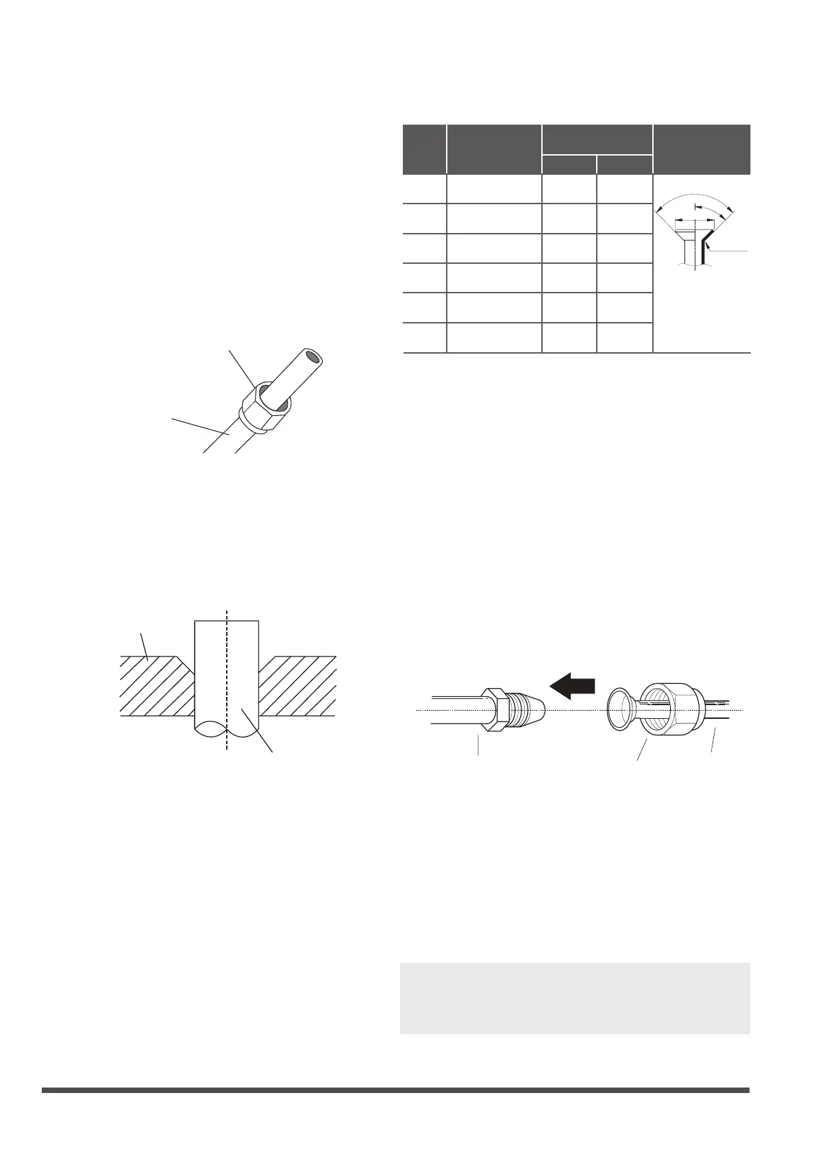
3. Place are nuts on both ends of pipe.
Make sure they are facing in the right
direction, because you can’t put them on
or change their direction after aring. See
Fig. 11.3
Flare nut
Copper pipe
Fig. 11.3
4. Remove PVC tape from ends of pipe when
ready to perform aring work.
5. Clamp are form on the end of the pipe.
The end of the pipe must extend beyond
the are form.
Flare form
Pipe
Fig. 11.4
6. Place aring tool onto the form.
7. Turn the handle of the aring tool
clockwise until the pipe is fully ared. Flare
the pipe in accordance with the dimensions
shown in table 11.1.
Table 11.1: PIPING EXTENSION BEYOND
FLARE FORM
8. Remove the aring tool and are form,
then inspect the end of the pipe for cracks
and even aring.
Step 4: Connect pipes
Connect the copper pipes to the indoor unit rst,
then connect it to the outdoor unit. You should
rst connect the low-pressure pipe, then the
high-pressure pipe.
1. When connecting the are nuts, apply a
thin coat of refrigeration oil to the ared
ends of the pipes.
2. Align the center of the two pipes that you
will connect.
Indoor unit tubing
Flare nut
Pipe
Fig. 11.6
3. Tighten the are nut as tightly as possible
by hand.
4. Using a spanner, grip the nut on the unit
tubing.
5. While rmly gripping the nut, use a torque
wrench to tighten the are nut according
to the torque values in table 11.1.
NOTE: Use both a spanner and a torque
wrench when connecting or disconnecting
pipes to/from the unit.
Pipe
gauge
Tightening
torque
Flare dimension (A)
(Unit: mm/Inch)
Flare shape
Min. Max.
Ø 6.4
R0.4~0.8
45
°
±
2
90
°
±
4
A
Fig. 11.5
Ø 9.5
Ø 12.7
Ø 15.9
Ø 19.1
Ø 22
65-67 N.m
(663-683 kgf.cm)
23.2/0.91 23.7/0.93
75-85N.m
(765-867 kgf.cm)
26.4/1.04 26.9/1.06
18-20 N.m
(183-204 kgf.cm)
8.4/0.33 8.7/0.34
25-26 N.m
(255-265 kgf.cm)
13.2/0.52 13.5/0.53
35-36 N.m
(357-367 kgf.cm)
16.2/0.64 16.5/0.65
45-47 N.m
(459-480 kgf.cm)
19.2/0.76 19.7/0.78
 Loading...