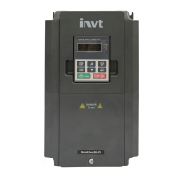
Do you have a question about the INVT GD10-0R7G-S2-B and is the answer not in the manual?
Defines hazard levels (Danger, Warning, Note) and role of qualified electricians.
Safety measures during VFD operation, startup, and maintenance.
Detailed technical specifications covering power, performance, and interfaces.
Procedures for correctly wiring the VFD's electrical connections.
Schematic for connecting the main power and motor circuits.
Instructions for wiring control input and output signals.
Safeguards for input power cables against short circuits.
Detailed process for changing VFD function code parameters.
Core operational parameters for basic VFD functionality.
Settings for speed mode, running commands, and maximum output frequency.
Parameters controlling the VFD's start and stop behavior.
Parameters for start modes, stop modes, and DC braking functions.
Configuration settings for the motor.
Parameters defining motor power, frequency, speed, voltage, current, and impedance.
Settings for motor overload and underload protection.
Parameters for SVPWM control strategy.
Parameters for setting V/F curves and torque boost compensation.
Parameters for configuring digital and analog input terminals.
Assigning specific functions to digital input terminals S1-S5.
Parameters for configuring digital and analog output terminals.
Assigning functions to output terminals Y and RO relay.
Parameters related to the Human-Machine Interface (keypad and display).
Instructions for setting up and managing user password protection.
Parameters for logging data related to the current fault.
Parameters for advanced operational features and functions.
Parameters for implementing and tuning PID control loops.
Core PID control loop parameters: reference, feedback, output, and gain.
Parameters for tuning PID control loops: integral, differential, sampling, and deviation.
Parameters for controlling the VFD speed in multiple steps.
Parameters for VFD protection and fault handling.
Protection settings against transient power loss events.
Parameters for overvoltage and current limit protection.
Settings for overload and underload pre-alarm detection.
Parameters for setting up serial communication protocols.
Setting the Modbus communication address for the VFD.
Detailed explanation of the RTU communication mode.
Structure and format of RTU data frames for communication.
Methods used for error detection in RTU communication frames.
Explanation of RTU command codes and data fields.
Details on using the 03H command to read VFD parameters.
Details on using the 06H command to write VFD parameters.
Using the 08H command for diagnostic queries of the VFD.
Understanding the structure and definition of communication data addresses.
Meanings of the VFD's error response codes.
Practical examples of Modbus read and write operations.
Examples demonstrating how to read VFD data using command 03H.
How ambient temperature affects the VFD's rated output current.
Guidelines for selecting braking resistors based on VFD model and usage.
| Rated Power | 0.75kW |
|---|---|
| Frequency Range | 0-400Hz |
| Protection Level | IP20 |
| Communication Interface | RS485 |
| Input Voltage | 380V |
| Cooling Method | Fan cooling |


