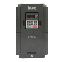
Do you have a question about the INVT GD10-1R5G-S2-B and is the answer not in the manual?
General safety rules for VFD operation and maintenance.
Detailed technical specifications of the VFD.
Guidelines for the physical installation of the VFD.
Guidelines for wiring the VFD's electrical connections.
Instructions for connecting the main power and motor circuit wiring.
Instructions for wiring the control circuit of the VFD.
Methods for protecting VFD wiring against faults.
How the keypad displays parameters, status, and fault information.
Procedure for entering and modifying VFD function codes.
General operations that can be performed using the VFD keypad.
Step-by-step guide to changing VFD parameters.
Parameters for fundamental VFD operations like speed control and command sources.
Parameters for controlling VFD start, stop, and braking behaviors.
Parameters related to motor configuration and protection.
Parameters for V/F curve, torque boost, and vibration control.
Parameters for configuring digital and analog input terminals.
Parameters for configuring digital and analog output terminals and relays.
Parameters for keypad operation, password, display, and fault logging.
Parameters for configuring PID control loops for process automation.
Parameters for setting multiple speed levels for the VFD.
Parameters for VFD overvoltage, overload, and fault protection settings.
Strategies and procedures to prevent VFD faults and ensure reliable operation.
Procedures for diagnosing, resetting, and resolving VFD faults.
How the VFD indicates alarms and faults via LEDs and display.
Detailed guide to identify, diagnose, and resolve common VFD faults.
Explains the Modbus protocol basics for VFD communication.
Details the communication modes and physical layers used by the VFD.
Describes the RTU communication mode and its characteristics.
Details Modbus RTU command codes, data formats, and error handling.
| Rated Power | 1.5 kW |
|---|---|
| Rated Current | 7.0 A |
| Frequency Range | 0-400 Hz |
| Protection Level | IP20 |
| Cooling Method | Air cooling |


