Goodrive20 inverters Function Parameters
73
Function
code
Name Detailed instruction of parameters
Default
value
Modify
Setting range:0.0~100.0%
P09.09
Output upper
limit of PID
These parameters are used to set the upper and lower limit
of the PID adjustor output.
100.0 % corresponds to Max. Frequency or the Max.
Voltage of ( P04.31)
Setting range of P09.09: P09.10~100.0%
Setting range of P09.10: -100.0%~P09.09
100.0%
Output lower
limit of PID
0.0%
○
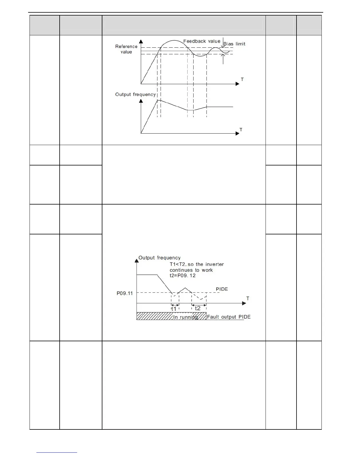
Feedback
offline
detection value
Set the PID feedback offline detection value, when the
detection value is smaller than or equal to the feedback
offline detection value, and the lasting time exceeds the set
value in P09.12, the inverter will report “PID feedback offline
fault” and the keypad will display PIDE.
Setting range of P09.11: 0.0~100.0%
Setting range of P09.12: 0.0~3600.0s
0.0% ○
Feedback
offline
detection time
selection
0x00~0x11
LED ones:
0:Keep on integral adjustment when the frequency achieves
the upper and low limit; the integration shows the change
between the reference and the feedback unless it reaches
the internal integral limit. When the trend between the
reference and the feedback changes, it needs more time to
offset the impact of continuous working and the integration
will change with the trend.
0x0001
 Loading...