EasyManua.ls Logo

INVT GD20-0R4G-S2

INVT GD20-0R4G-S2
140 pages
To Next Page IconTo Next Page
To Previous Page IconTo Previous Page
Loading...
Goodrive20 inverters Function Parameters
75
Function
code
Name Detailed instruction of parameters
Default
value
Modify
P10.03
The running
time of stage
0
When selecting simple PLC running, set P10.02~P10.33 to
define the running frequency and direction of all stages.
Note: The symbol of multi-step determines the running
direction of simple PLC. The negative value means reverse
rotation.
multi-step speeds are in the range of --f
max
~f
max
and it can be
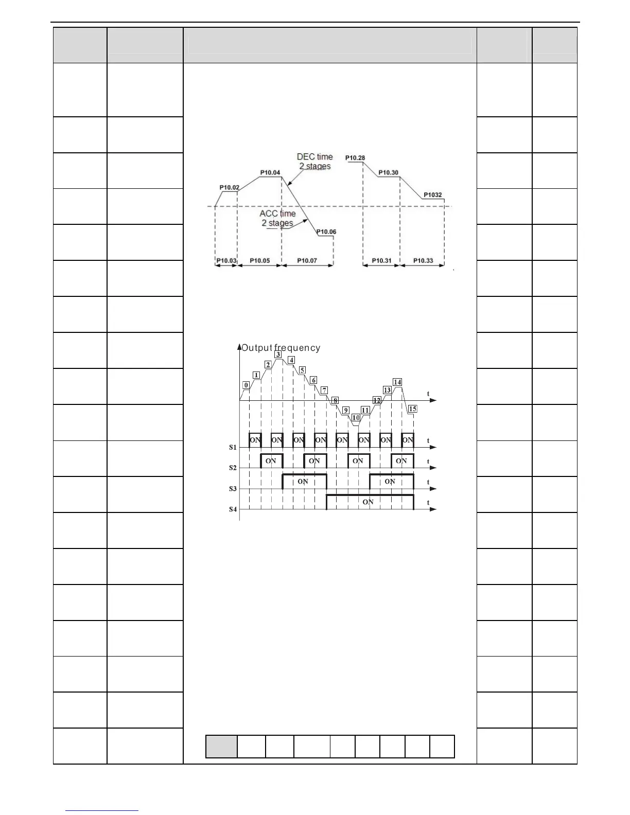
Goodrive20 series inverters can set 16 stages speed,
selected by the combination of multi-step terminals 1~4,
corresponding to the speed 0 to speed 15.
When S1=S2=S3=S4=OFF, the frequency input manner is
selected via code P00.06 or P00.07. When all
S1=S2=S3=S4 terminals aren’t off, it runs at multi-step
which takes precedence of keypad, analog value,
high-speed pulse, PLC, communication frequency input.
Select at most 16 stages speed via the combination code of
S1, S2, S3, and S4.
The start-up and stopping of multi-step running is
determined by function code P00.06, the relationship
between S1,S2,S3,S4 terminals and multi-step speed is as
following:
S1
OFF
ON
OFF
ON
OFF
ON
OFF
ON
0.0s
P10.04
Multi-step
speed 1
0.0%
P10.05
The running
time of stage 1
0.0s
P10.06
Multi-step
speed 2
0.0%
P10.07
The running
time of stage 2
0.0s
P10.08
Multi-step
speed 3
0.0%
P10.09
The running
time of stage 3
0.0s
P10.10
Multi-step
speed 4
0.0%
P10.11
The running
time of stage 4
0.0s
P10.12
Multi-step
speed 5
0.0%
P10.13
The running
time of stage 5
0.0s
P10.14
Multi-step
speed 6
0.0%
P10.15
The running
time of stage 6
0.0s
P10.16
Multi-step
speed 7
0.0%
P10.17
The running
time of stage 7
0.0s
P10.18
Multi-step
speed 8
0.0%
P10.19
The running
time of stage 8
0.0s
P10.20
Multi-step
speed 9
0.0%
P10.21
The running
time of stage 9
0.0s

Table of Contents

Related product manuals