Goodrive350 IP55 High-ingress Protection Series VFD Optional peripheral accessories
-354-
Only qualified electricians are allowed to perform the wiring. Otherwise, damage
to the VFD or brake components may be caused.
Read the brake resistor or unit instructions carefully before connecting them to
the VFD.
Connect brake resistors only to the terminals PB and (+), and brake units only to
the terminals (+) and (-). Do not connect them to other terminals. Otherwise,
damage to the brake circuit and VFD and fire may be caused.
Connect the brake components to the VFD according to the wiring diagram. If
the wiring is not properly performed, damage to the VFD or other devices may
be caused.
Goodrive350 IP55 high-ingress protection series VFDs of 037G/045P or lower are equipped
with built-in brake units, Select brake resistors according to the specific requirements (such as
the brake torque and brake usage requirements) on site.
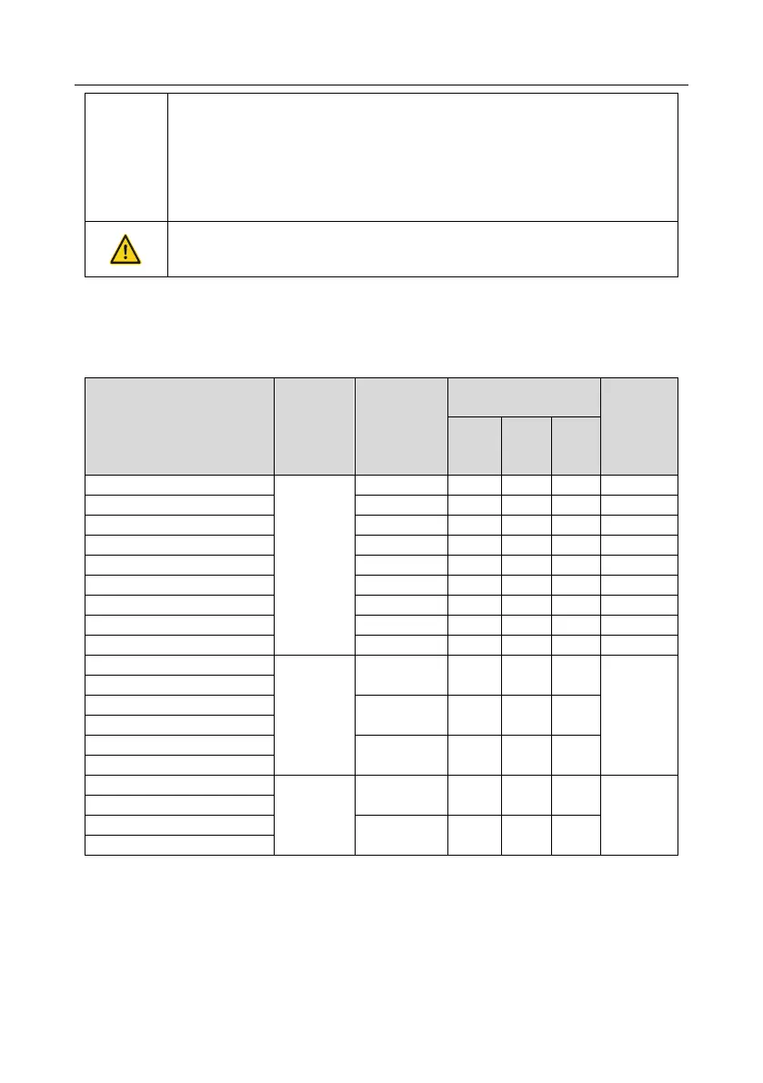
Table D-8 Brake unit signals
Resistance
applicable
for 100%
brake torque
(Ω)
Dissipated power of
brake resistor (kW)
Min.
allowable
brake
resistance
(Ω)
Note:
1. Select brake resistors according to the resistance and power data provided by our company.
2. The brake resistor may increase the brake torque of the VFD. The preceding table
describes the resistance and power for 100% brake torque, 10% brake usage, 50% brake
usage, and 80% brake usage. You can select the brake system based on the actual
operation conditions.
 Loading...