Goodrive100-PV Series Solar Pumping VFD Installation guidelines
11
3PH (1PH) AC input terminals, connected to the grid
Note: Use the screws equipped with the VFD for wiring.
Solar cell panel input terminals
3PH/1PH AC output terminals, connected to the pump
motor
Note: 1PH motors must connect to terminals U and W.
Safety protection grounding terminal. Each VFD must
be grounded
Description for -SS2 single-phase output models
1) Generally, the output terminals U and W of the VFD connect to the phase cables of the
single-phase motor.
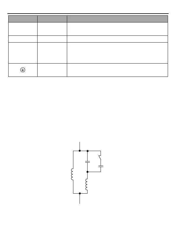
2) If the single-phase pump cannot be started, the two-phase control method must be used,
and the start-up and running capacitors (if any) of the motor must be removed. The figure
below shows the internal wiring of the common single-phase motor. In the figure, L1, L2, C1,
and C2 indicate the running winding, start-up winding, running capacitor, and start-up
capacitor. When the motor speed exceeds 75% of the rated speed, the start-up capacitor is
switched off.
Internal wiring of the single-phase motor winding after removing the starting and running
capacitor:

 Loading...


