EasyManuals Logo

INVT HT33 Series User Manual

INVT HT33 Series
44 pages
To Next Page IconTo Next Page
To Previous Page IconTo Previous Page
Page #13 background imageLoading...
Page #13 background image
-13-
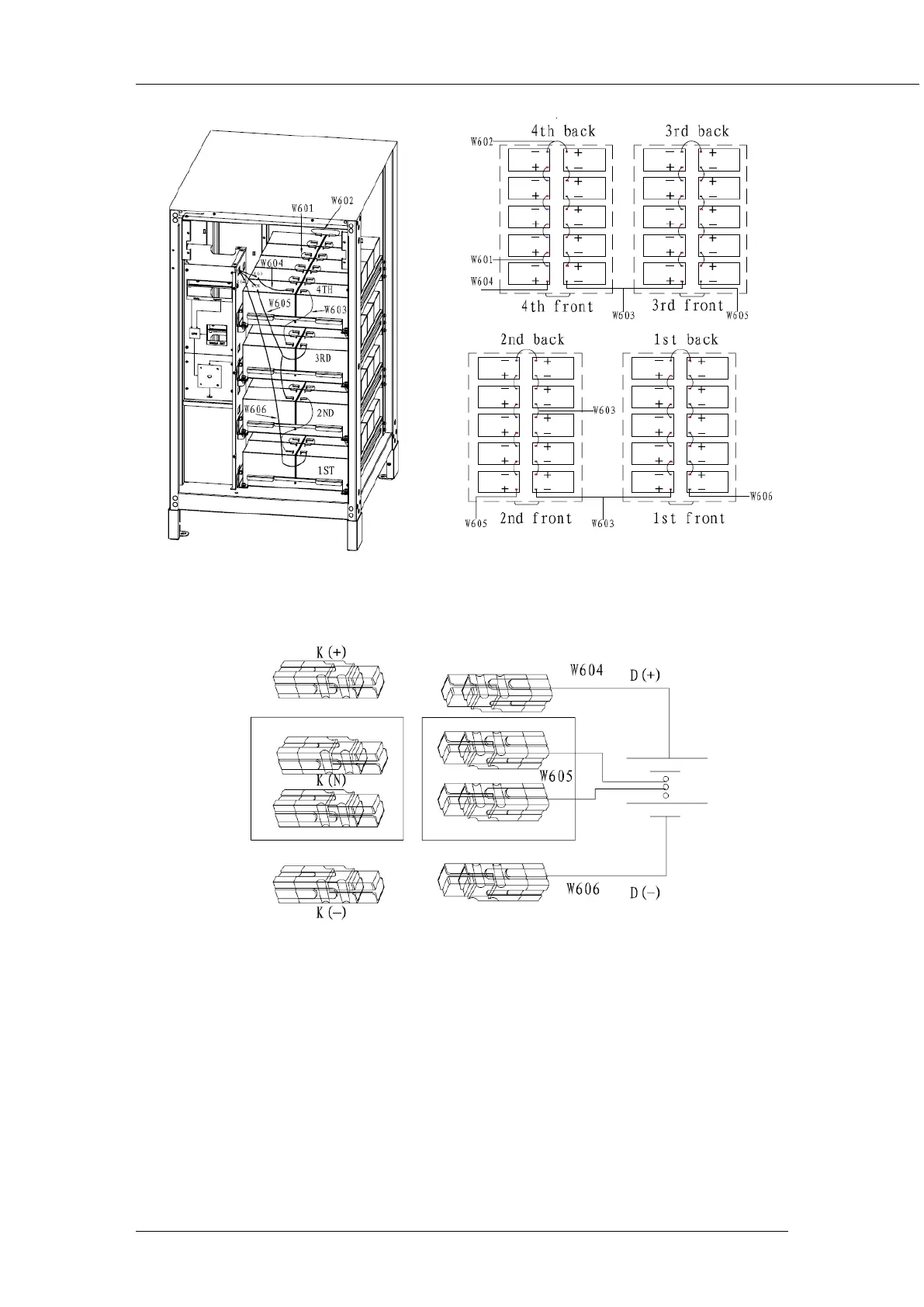
Fig 2-5a Build-in battery connection diagram
The UPS and battery are connected by Anderson terminals as shown below, according to the mark
of cables, connect cables W404,W405,W406 to K(+),K(N),K(-).
Fig 2-5b Build-in battery connection diagram
2.6 Control and Communication Cabling
As shown fig. 2-6, the dry contact interface (J2-J10), communication interface (RS232 interface, 485
interface and SNMP card interface) and LBS interface.

Table of Contents

Questions and Answers:

Question and Answer IconNeed help?

Do you have a question about the INVT HT33 Series and is the answer not in the manual?

INVT HT33 Series Specifications

General IconGeneral
BrandINVT
ModelHT33 Series
CategoryUPS
LanguageEnglish

Related product manuals