-17-
J8
B
A
T
_
L
O
W
_
N
C
B
A
T
_
L
O
W
_
N
O
G
N
D
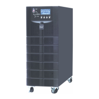
Fig 2-11 Battery warning dry contact interface diagram
Table 2-6 Battery warning dry contact interface description
Battery warning relay (normally closed) will be open during warning
Battery warning relay (normally open) will be closed during warning
Center of battery warning relay
2.6.6 Integrated Warning Output Dry Contact Interface (Optional)
J9 is the integrated warning output dry contact interface, when one or more than one present
warning is triggered, the system will send integrated warning information, and provide an auxiliary dry
contact signal via the isolation of a relay. The interface diagram is shown in fig 2-12, and description is
shown in table 2-7
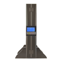
Fig 2-12 Integrated warning dry contact interface diagram
Table 2-7 Integrated warning dry contact interface description
Integrated warning relay (normally closed) will be open during warning
Integrated warning relay (normally open) will be closed during warning
Centre of integrated warning relay
2.6.7 Mains Failure Warning Output Dry Contact Interface (Optional)
J10 is the output dry contact interface for mains failure warning, when the mains fails, the system
will send a mains failure warning information, and provide an auxiliary dry contact signal via the isolation
of a relay. The interface diagram is shown in fig 2-13, and description is shown in table 2-8.
 Loading...