DE
SAF-MI-LBK-SBV-multi-v2.0-print-26000041 |© 2020-2021 Inxpect SpA Installationsanleitung 29
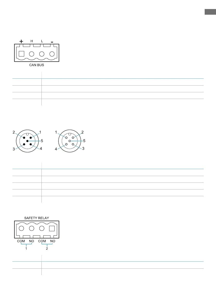
Pinbelegung der Anschlussleisten und Stecker
CAN-Bus-Anschlussleiste LBK-C22 und ISC-B01
Symbol Beschreibung
+ + 12 VDC
H CAN H
L CANL
- GND
Info: Die Kabel müssen eine Betriebstemperatur von mindestens 80°C für LBK-C22 und mindestens 70°C
für ISC-B01 haben.
M12-Steckverbinder für CAN-Bus LBK-C22 und ISC-B01
Stecker Buchse
Pin Funktion
1 Abschirmung, zu erden an der Versorgungsklemme der Steuerungseinheit.
2 + 12 VDC
3 GND
4 CAN H
5 CANL
Anschlussleiste Sicherheitsausgänge LBK-C22
Symbol Beschreibung
COM Gemeinsamer Sicherheitsausgang 1
NO Relaisausgang normalerweise offen