IT
SAF-MI-LBK-SBV-multi-v2.0-print-26000041 |© 2020-2021 Inxpect SpA Istruzioni per l'installazione 5
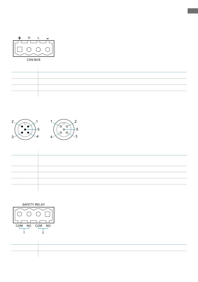
Piedinatura morsettiere e connettori
Morsettiera CAN bus LBK-C22 e ISC-B01
Simbolo Descrizione
+ + 12 V cc
H CAN H
L CANL
- GND
Nota: i cavi devono avere una temperatura di esercizio di almeno 80 °C per LBK-C22 e di almeno 70 °C
per ISC-B01.
Connettori M12 CAN bus LBK-C22 e ISC-B01
Connettore maschio Connettore femmina
Pin Funzione
1 Schermatura, da collegare a terra sulla morsettiera di alimentazione dell'unità di
controllo.
2 + 12 V cc
3 GND
4 CAN H
5 CANL
Morsettiera uscite di sicurezza LBK-C22
Simbolo Descrizione
COM Comune uscita sicurezza 1
NO Uscita relè normalmente aperto