30ACi
Battery Back-Up System
OPERATION MANUAL
Dated: 07/23/2013
Document Name: 30ACi_OM
Page 4 of 12
Register your product at www.sumpro.com
toolS needed
A pipe wrench, insulated pliers, insulated adjustable
wrench, and insulated screwdriver will be needed.
InStallatIon InStructIonS
Remove all packaging from the box. It should include:
an inverter, battery box, pig tail with Anderson
connector, inverter power cord and pump with Ion
®
switch.
Find a suitable place to set the unit. Keep in mind that
the unit should be placed in an area where water and
moisture will not splash or drip on the unit, the fan inlet
on the sides of the enclosure will not be obstructed
and where a properly grounded three prong dedicated
receptacle is within reach of the power cord.
• Remove watches, rings, or other metal objects.
• Use tools with insulated handles
• Do not lay tools or metal parts on top of batteries
1. Install the 12 volt deep cycle marine battery
into the plastic battery box. Make sure that the
MCB (main circuit breaker) on the back of your
inverter is in the OFF position.
2. Connect the black negative (-) wire of the pig
tail to the negative (-) terminal of the 12 volt
battery.
3. Connect the red positive (+) wire of the pig tail
to the positive (+) terminal of the 12 volt battery.
4. Lay wires on over the short side of the battery
box so the Anderson connector is on the outside
of the battery box. Install the plastic cover on
the battery box so that the red and black wires
come out of the battery box and set the inverter
on top of the battery box cover.
5. Plug the Anderson connector from the inverter
into the Anderson connector from the battery,
insuring that the wire colors match on both
sides.
6. Install the sump pump in the sump pit and place
the sump cover back on the sump pit so that
the pump switch cord and pump power cord
reach the inverter.
7. Plug the switch cord into the back of the inverter
Mains A.C. Lower Voltage Limit 90 VAC ± 5V
Output Voltage with Full Load 110 - 120V ± 10 V
Battery Lower Voltage Limit 10.5 VOC ± 0.2 V
Output Frequency
Main Output Frequency Same as Input
Battery Charger Boost Voltage 13.7 ± 0.2 V
Overload 130% ± 3% (With Auto
Reset Function)
Model
Output
Discharge
(inch)
Rated Maximum
Dimensions
L x W x H
Weight
(lbs)
HP Amp Head (feet) Flow (GPM) Head Flow (GPM)
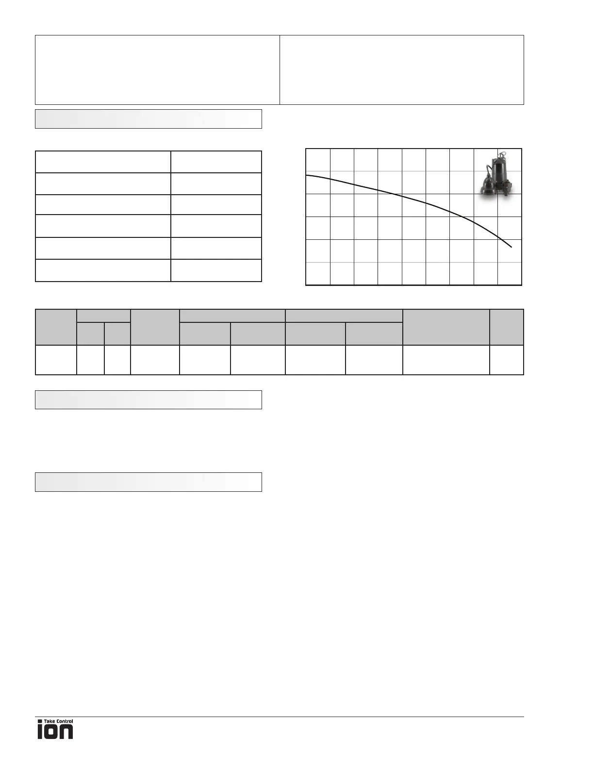
WC-33 1/3 4.0 1-1/2 NPT 10 41 0 GPM @ 24’ 46 GPM @ 0’ 9 x 6-1/2 x 10” 18
Inverter Specications
Pump Specications
Pump Performance Curve
Head - feet
Capacity - US GPM
0
25
15
5
10
20
0 252015105 30 35 40 45
technIcal SpecIfIcatIonS