3
iOptron Corp. | 6E Gill Street | Woburn, MA 01801 USA | (781) 569-0200 | www.iOptron.com
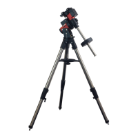
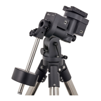
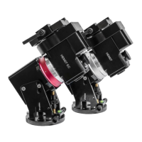
from one to the other, both the Latitude Position Bolt
and the Latitude Locking Screws need to be moved to
the correct locations (see photos below).
Loosen the Latitude Locking Screws just enough to
adjust the latitude setting to 40°. Move the Latitude
Locking Screws with washers (one on each side) to
the new locations revealed, do not tighten them just
yet.
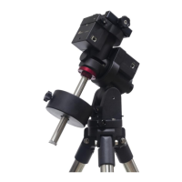
Unthread and remove the Position Bolt to its new
location. Adjust the Latitude Adjustment Knob while
holding the brass eyebolt until it lines up with the
Position Bolt. Secure the Latitude Position Bolt.
4. Install Counterweight (CW) Shaft: Thread the CW
shaft into the CW shaft mounting holes.
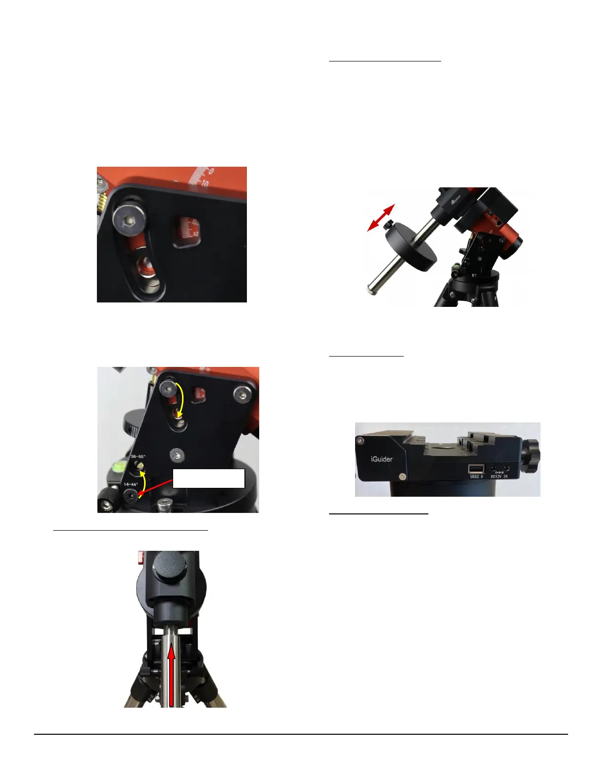
5. Install Counterweight(s): Before putting on CW,
make sure the mount is at its zero position, i.e., CW
shaft points to the ground. Disengage the R.A. Gear
Switch to set the R.A. axis free before loading the
CW. Remove the CW Safety Cap at the end of CW
Shaft. Glide the CW over the shaft. Tighten the CW
Locking Screw to hold the CW in place. Place the
Safety Cap back onto the shaft. Move the CW to the
bottom of the shaft and tighten the CW locking
Screw.
You may need more CW for heavier payloads, or a
smaller CW for lighter scopes.
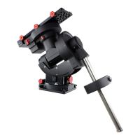
6. Install Telescope:
A GEM45 is equipped with a 6” Vixen/Losmandy-D
dual saddle. It can receive either a Vixen or a
Losmandy-D plate. A GEM45AG has an iGuider
TM
guiding system on the dovetail saddle.
7. Balancing the Payload: After attaching the scope and
accessories, the mount head assembly must be
balanced in both DEC and RA axes to ensure
minimum stresses on the mount driving mechanism.
CAUTION: The telescope may swing freely when the
R.A. or DEC Gear Switch is disengaged. Always hold
on to the mount and/or telescope assembly before
releasing the Gear Switches to prevent it from
swinging, which can cause personal injuries and/or
equipment damages.
Set the mount at Zero Position. Disengage both RA
and DEC gear switches and move the mount to
horizontal position to check balance. Return to Zero
Position for balance adjustment. Balance the DEC axis
by moving the scope with accessories back and forth