D
Daniel WilliamsAug 14, 2025
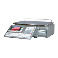
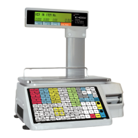
What to do if power is not supplied to my ISHIDA BC-4000?
- SSherry AriasAug 15, 2025
If your ISHIDA Scales are not receiving power, here are a few things to check: * Ensure the power supply plug is securely inserted. * Replace the fuse if it has blown. * Inspect and, if necessary, replace the main board, power supply unit, or power switch.