EasyManua.ls Logo

ISHIDA IWQ Series User Manual

ISHIDA IWQ Series
55 pages
To Next Page IconTo Next Page
Page #1 background imageLoading...
Page #1 background image
IWQ Series
Service Manual
First Edition
Manual No. 0153A
Read this manual thoroughly and do not perform installation, operation,
maintenance, or inspection unless you fully understand all contents.
Keep this manual in a safe place where you can refer to it easily while
installing, operating, and carrying out maintenance or inspections.
Warning
This manual is for use by service personnel of our company or qualified to
perform maintenance services for this machine.

Questions and Answers:

ISHIDA IWQ Series Specifications

General IconGeneral
BrandISHIDA
ModelIWQ Series
CategoryScales
LanguageEnglish

Summary

Chapter 1. Product Overview

1.1 Product Overview

Details about the IWQ Series waterproof electronic scale, its functions, and safety features.

1.2 Standard Specifications

Lists technical specifications like weighing capacity, accuracy, dimensions, power source, and environmental conditions.

1.3 Appearance

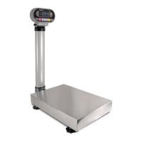
Illustrates the physical appearance of the IWQ-150 model, showing its main components.

1.4 Appearance of Operation Panel

Shows the layout and buttons of the operation panel common to IWQ-150 and IWQ-30.

Chapter 2. Installation, Placement and Setup

2.1 Outer Dimensions

Provides detailed dimensional drawings for both IWQ-150 and IWQ-30 models in millimeters.

2.2 Procedures of Installation and Placement

Details the step-by-step process for unpacking and mounting the display pole and other components.

Chapter 3. Each Setting Mode

3.1 Configuration of Modes

Outlines the different operational modes (Normal, Registration, Setup, Test) and their functions.

3.2 Setup Mode

Introduces the Setup Mode and its various settings for printer and RS232C configurations.

3.2.1 Setup mode list

Details the specific settings (F1-F16) available within Setup Mode, including their functions and values.

3.2.2 Start-up of Setup Mode, setup, and end of setup

Explains the procedure for entering, configuring, and exiting the Setup Mode.

3.2.3 Input command format

Describes the format for commands sent to the scale, including execution and data demand commands.

3.2.4 Output format

Details the available output formats for data transmission and printing, including specific patterns.

3.3 Test Mode

Introduces the Test Mode and its purpose for verification and setup during maintenance.

3.3.1 Start-up and end of Test Mode

Explains how to enter and exit the Test Mode, including specific key presses.

3.3.2 C1 Mode : Country No. Scale No. and Span Adjustment

Details the process for setting country number, scale number, and performing span adjustment.

3.3.3 C2 Mode .... Key check

Describes how to perform a key check to verify the functionality of each button on the operation panel.

3.3.4 C3 Mode .... Display check (1)

Explains how to check if all segments of the fluorescent indicator tubes and LEDs light up simultaneously.

3.3.5 C4 Mode .... Display check (2)

Details how to check each segment of the fluorescent indicator tubes for proper lighting, identifying potential short circuits.

3.3.6 C5 Mode .... Program No. display

Describes how to display the current program number on the scale.

3.3.7 C6 Mode .... E2ROM initialization (Registration set data/all)

Guides through the process of initializing the E2ROM, including registration, setup, and scale data.

3.3.8 C7 Mode .... Individual setup of country specifications and weighing conditions

Explains how to individually set country specifications and weighing conditions.

3.3.9 C8 Mode .... E2ROM data readout

Details how to read data from the E2ROM, specifying the address range and navigation.

3.3.10 C9 Mode A/D flickering check, I/F inspection mode

Covers A/D flickering checks and I/F inspection modes for factory testing.

3.4 Country No. List

3.5 Scale No. List

3.6 EEPROM Map

3.6.1 EEPROM (0 ~ 127) data format

Provides a detailed map of the EEPROM, listing addresses, data contents, and their ranges.

3.6.2 Measurement conditions setup table

Details the setup table for measurement conditions, including address, weight, data contents, and data range.

Chapter 4. Hardware Configuration

4.1 Mechanisms

Outlines the mechanical components of the scale, including the display, scale, and pole sections.

4.1.1 Display section (IWQ-30/150 common)

Details the parts and assembly of the display section common to both IWQ-30 and IWQ-150 models.

4.1.2 Scale section

Illustrates the parts and assembly of the scale section for both IWQ-30 and IWQ-150 models.

Load Cell

Describes the specifications and construction of the Load Cell AT-50 (IWQ-30) and AT-200 (IWQ-150).

4.1.3 Display pole section

Details the parts and assembly of the display pole section, including the bracket and adjusting knob.

4.2 Electric Concerns

Introduces the electrical aspects of the scale, covering main boards, A/D boards, and power supplies.

4.2.1 Block diagram

Presents a block diagram showing the interconnection of main board, A/D board, I/F board, and load cell.

4.2.2 Main board P-932-

Details the main board P-932, including its memory switch and connectors (XJ1, XJ2, XJ3).

4.2.3 A/D board P-933

Describes the A/D board P-933, including its major parts and connectors (XJ1, XJ2).

4.2.4 I/F board P-934-1 (option)

Details the optional I/F board P-934-1, its components, and connectors (XJ1, XJ2, XJ3, XJ4).

4.2.5 SW Power supply

Explains the specifications and connectors of the switching power supply unit.

Chapter 5. Maintenance

5.1 Periodical Replacement Parts

States that no periodical parts replacement is needed within a five-year product life, except for gasket packing.

5.2 Replacing and Adjusting Load Cell

Provides specifications for load cells and outlines the process for replacing and adjusting them.

5.3 Troubleshooting

Lists common phenomena, their causes, and suggested measures for troubleshooting issues.

Chapter 6 Others (Appendix)

6.1 RS-232C Connecting Cables (Optional)

Introduces optional RS-232C cables for connecting the scale to other devices.

6.1.1 RS232C cable DSUB9Pin

Details the RS232C cable with a DSUB9Pin connector, including pinouts and part numbers.

Related product manuals