EasyManua.ls Logo

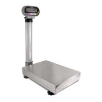
ISHIDA IGB-60 User Manual

ISHIDA IGB-60
47 pages
To Next Page IconTo Next Page
Page #1 background imageLoading...
Page #1 background image
IGB/IGX Series
(Overseas Specifications)
Service Manual
The First Edition
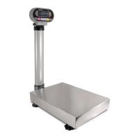
IGB Series IGX Series
This manual is for use by service personnel of our company or qualified to
perform maintenance services for this machine. Use by anyone except the
above personnel is not permitted.
Manual No. 085-3435-07
Read this manual thoroughly and do not perform installation, operation,
maintenance, or inspection unless you fully understand all of the contents.
Keep this manual in a safe place where you can refer to it easily while
installing, operating, and carrying out maintenance or inspections.
Warning
86547

Questions and Answers:

ISHIDA IGB-60 Specifications

General IconGeneral
Capacity60 kg
Readability10 g
DisplayLCD
InterfaceRS-232C
Auto Power OffYes
Overload Capacity120 kg
Power SupplyAC 100V~240V, 50/60Hz

Summary

OUTLINE

Warning Symbols

Defines danger, warning, and caution symbols for safety information.

Explanatory Symbols

Defines symbols like Note, Reference, and Information for manual clarity and understanding.

Manual Usage Guidelines

Specifies the manual is for servicing personnel and prohibits unauthorized use or copying.

Chapter 1 Product Overview

Machine Outline

Describes common software, functions, and differences between IGB and IGX series models.

Standard Specifications

Details weighing capacity, graduation, accuracy, material, and environmental conditions for IGB/IGX.

Appearance

Illustrates the physical appearance of IGB and IGX series scales, showing key components.

Display Unit

Details the display layout and indicators for IGB and IGX series, including weight, units, and status marks.

Outer Dimensions

Provides detailed dimensional drawings and measurements for the IGB/IGX series scales.

Chapter 2 Test Mode

Operation

Explains how to operate and navigate within the Test Mode, including starting and ending specific modes.

Starting Each Mode

Illustrates the procedure for entering Test Mode and its various sub-modes.

Ending Test Mode

Describes the process to exit Test Mode and return to normal operation.

Test Mode Flow

Presents a flowchart illustrating the sequence of operations and transitions between different test modes.

Key Functions

Details the function of each key within the Test Mode operations.

Mode List

Lists all available Test Modes (C1-C9) with a brief description of their purpose.

C1 Mode: Country, Scale, Zero, Span

Covers setting country number, scale number, zero point, and span adjustment.

C1 Mode Operation Procedure

Details the step-by-step procedure for operating C1 Mode, including setting country, scale, and adjustments.

C1 Mode Span Adjustment

Explains how to perform span adjustment using specific weights and display feedback.

C1 Mode Saving Data

Describes the procedure to save configured data into E2ROM using the memory switch.

C1 Mode Finishing Procedure

Outlines the final step to exit the adjustment procedure.

C1 Mode Fine Span Adjustment

Details the steps for fine-tuning the span adjustment, including trimming up and down.

C2 Mode Key Check

Describes how to enter and perform a key check in C2 Mode, verifying key functionality.

C3 Mode Display Check 1 Simplified Check

Explains how to perform a simplified display check in C3 Mode, where all display segments are lit.

C4 Mode Display Check 2 Detailed Check

Details how to perform a detailed display check in C4 Mode, checking each segment lighting up.

C5 Mode Program No Display

Describes how to access and display the installed program number in C5 Mode.

C6 Mode RAM Clear and E2ROM Clear

Outlines the procedure for clearing RAM and E2ROM data, including initialization steps.

C7 Mode Weighing Condition Setting

Explains how to set weighing conditions, including country and scale numbers.

Weighing Condition Setting Table

Provides a detailed table mapping addresses, weights, items, and data values for setting weighing conditions.

C8 Mode E2ROM Data Reading

Details how to access and read data stored in E2ROM by navigating through addresses.

E2ROM Data

Lists the types of data stored in E2ROM, their addresses, data ranges, and remarks.

C9 Mode Board Inspection A/D Check I/F Check

Describes the procedure for board inspection including A/D and I/F checks, primarily for factory inspection.

Memory Switch

Chapter 3 Hardware Configuration

Mechanical Parts

Illustrates and labels the various mechanical components of the IGB/IGX series scale.

IGB Series Service Parts List

Lists all part numbers, names, and quantities for the IGB Series, aiding component replacement.

IGX Series Service Parts List

Lists all part numbers, names, and quantities for the IGX Series, aiding component replacement.

Load Cell

Shows an exploded view of the load cell assembly, illustrating its position within the scale's base.

Electric Parts IGB Series

IGB Block Diagram

Provides a block diagram showing electrical connections between Display Unit and Scale Unit for the IGB Series.

Main Board PS-018

Details the parts surface of the IGB Series main board (PS-018), including CPU and connectors.

Power Board PS-019

Shows the schematic diagram of the Power Board (PS-019) for the IGB Series.

Electric Parts IGX Series

IGX Block Diagram

Presents a block diagram showing the electrical layout of the IGX Series.

Main Board PS-016

Details the parts surface of the IGX Series main board (PS-016), including CPU and connectors.

Connector XJ3

Lists the pin assignments for connector XJ3, noting it is not used.

Program Memory Media

Describes the program memory media and compatibility notes for IGB/IGX main boards.

Chapter 4 Maintenance

Disassembly Procedure for Display Unit

Provides a step-by-step guide to disassemble the display unit, including removing knobs, seals, and screws.

Replacement of Main Board

Outlines the procedure for replacing the main board in both IGB and IGX series.

IGB Series

Details the specific steps for replacing the main board in the IGB Series.

IGX Series

Details the specific steps for replacing the main board in the IGX Series.

Replacing and Adjusting Load Cell

Explains how to replace the load cell, including specifications and the physical process.

Checking and Adjusting Gap of Four-corner Limit

Describes how to check and adjust the gap of the four-corner limit for different models.

Performing Zero Point and Span Adjustments

Refers to Section 2.2 "C1 Mode" for instructions on performing zero point and span adjustments.

Troubleshooting

Related product manuals