Manual No. 085-3435-07 35/45 IGB/IGX Series (Overseas Specifications) Service Manual
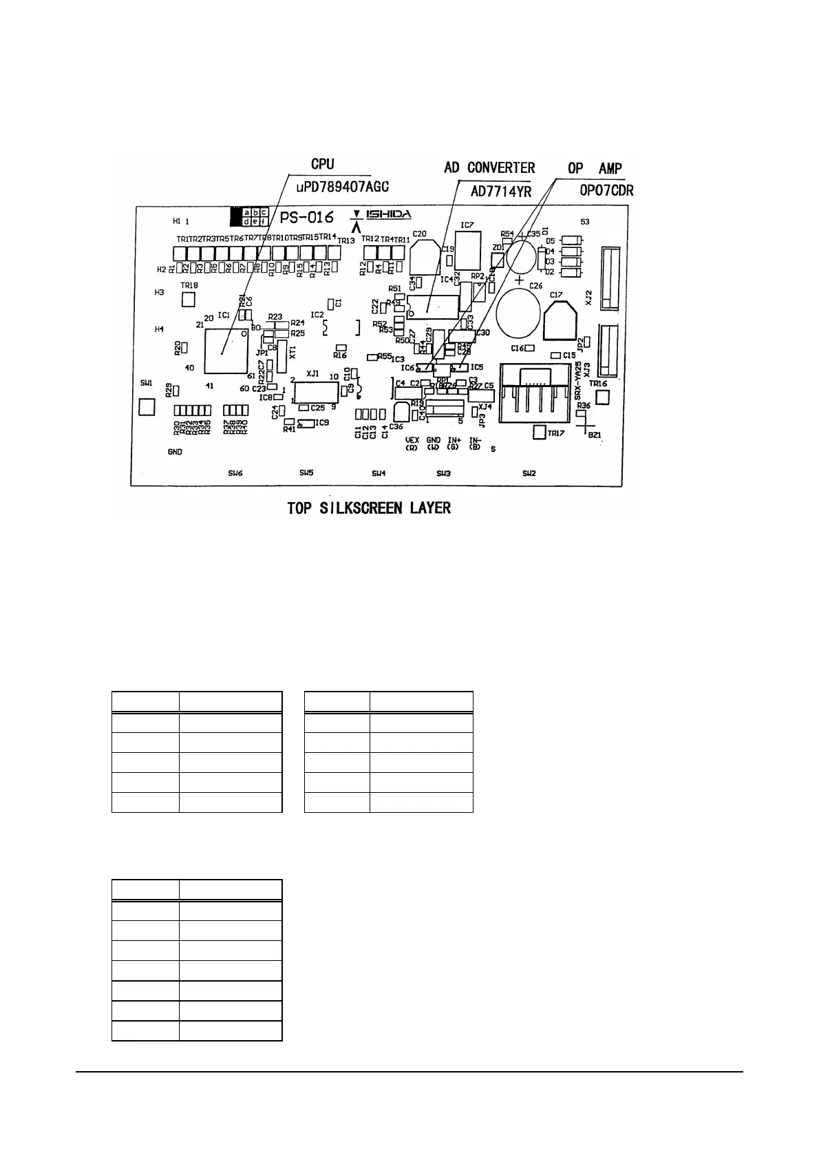
3.3.2 Main Board (PS-016)
Parts Surface of Main Board (The LCD and tact keys are installed on the soldering surface).
(1) SW1: Memory Switch
Used to write the data when performing initialization in Test Mode.
Used to save (write) the data in E2ROM after changing Country No. and Scale No., and performing
Span Adjustment.
(2) Connector XJ1
This connector is not used.
Pin No. Signal Name Pin No. Signal Name
1 IN1 6 NC
2 OUT4 7 RESET
3 OUT3 8 VPP
4 OUT2 9 GND
5 OUT1 10 VCC
(NC: Non connection)
(3) Connector XJ2
Power Input
Pin No. Signal Name
1 12VAC
2 0V
3 29VAC
4 0V
5 AC2
6 0V
7 AC1