44/54
IWQ Series Service Manual
(5) Connector XJ4
•
RS-232C input/output
PIN No.
Signal code Remarks
1BUZOUT
2DTROUT
3RXDIN
4TXDOUT
5GND
6NC
-FG
All outputs are at the
TTL level.
(6) Program memory medium
• Mask ROM 256 KB (Re-writing or replacing is not permitted.)
4.2.3 A/D board P-933
(1) Major parts
• Amplifier circuit (LC8000)
• A/D converter (AD7714YR)
(2) Connector XJ1
• Used for direct connection with the main
board.
Reference
Reference
Refer to “connector XJ2” of
the main board for PIN No.
and signal code.
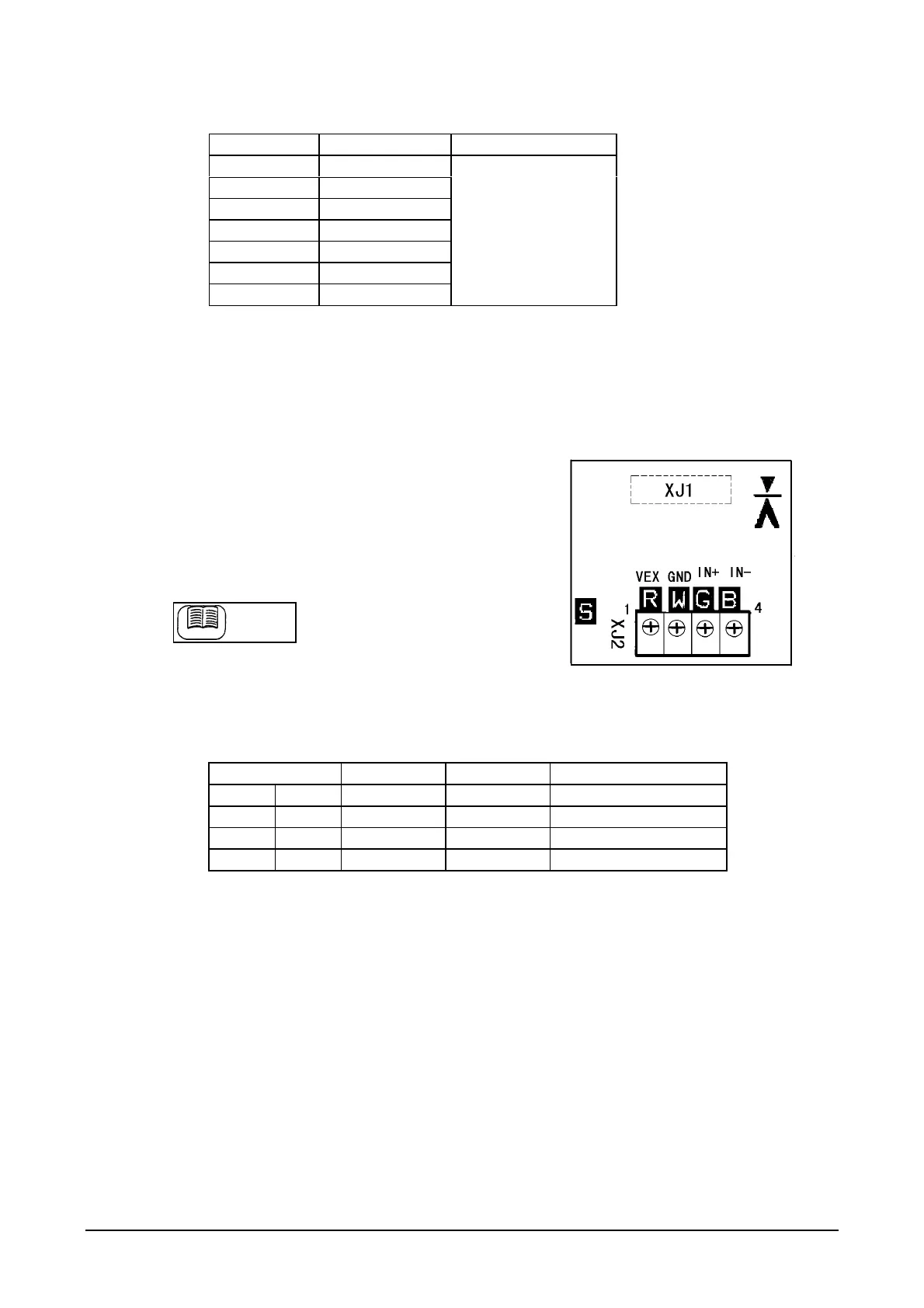
(3) Connector XJ2
• Load cell-connecting terminal with screws
• Tools: 2.5 mm Phillips screwdriver, or
flatblade screwdriver for adjustment.
[Soldering side]
Terminal No. Signal code Wire color Contents
1 R VEX Red Cell supply +5V
2 W GND White GND
3G IN+ Green
Input +
4 B IN- Blue Input −
 Loading...