Do you have a question about the Ismatec REGLO-CPF Digital and is the answer not in the manual?
Recommendation to flush pump head after each pumping process to prevent seizing.
Do not pump fluids with abrasive particles; observe filtration notes.
Piston fractures are not covered by the warranty.
Pump must operate within specified conditions; not for medical use or explosive atmospheres.
Ensure the circuit between mains and pump is earthed.
Manipulate pump head only when pump is off and disconnected from mains.
Do not open or remove the housing while the pump is operating.
Do not pump media with particles > 0.8 mm; select stroke volume accordingly.
Aggressive media may cause leaks; inspect pump regularly for leaks.
Fill pump head with liquid before operation; priming should not exceed 15 seconds dry.
Use only new fuses; ensure fuse holder is not short-circuited; be aware of tubing permeability and static charge.
Take safety measures if hose breakage or faulty connections could cause damage from leaks.
Repairs must be performed by skilled personnel aware of hazards.
2-year warranty on drive; pump head refers to manufacturer's manual; piston fractures excluded.
Warranted if installed/operated correctly; defective parts repaired/replaced free; claims excluded.
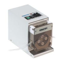
Valveless rotary piston dispensing pump.
Includes pump drive, power cord, manual, and specified pump head.
Available in 2-25 µl, 5-50 µl, and 10-100 µl capacities.
Inspect package and contents for damage; contact representative immediately.
RS232 IN/OUT, digital inputs (TTL), analog output for speed.
Supports 115/230 VAC; specifies fuse ratings for each voltage.
Steps to switch voltage via selector plate and replace fuses.
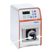
On/Off switch, LED display, Start/Stop, MODE, CAL, and adjustment keys.
LEDs indicate current mode: PUMP, DISP Volume, DISP Time, PAUSE Time, STROKE.
Controls pump start/stop, cycle start/interrupt, and mode selection.
Manages rotation direction, resets values, calibrates, and saves settings.
Increase/decrease values; fast read-out mode activation.
Displays LED test, firmware version, max stroke volume, and last used mode.
Procedure to reset all parameters to factory defaults.
Adjusts max stroke volume (25, 50, 100 µl) based on pump head model.
Calibrates the 0-point of the flow control ring for accurate dispensing.
Flow rate = Stroke Volume x Speed; offers flexibility in setting flow rates.
Small volume/high speed for low pulsation; large volume/low speed for viscosity/pressure.
Select STROKE mode, enter value, save, adjust flow control ring.
Select PUMP Flow rate mode, enter required rate, start pump.
Measure dispensed volume, enter value, save, adjust flow control ring.
Calibrate ascertained value, save, change mode to PUMP Flow rate, start pump.
Calibrate pump, connect titration handle, set flow rate, start pump.
Use the key to reset titration volume to zero.
Select DISP Time mode, enter desired time (0.1s to 999h), start pump.
Dispensing time and flow rate can be adjusted during the dispensing process.
Select DISP Volume mode, enter desired volume (µl or ml), start pump.
Pump slows before end; dispensing speed adjustable; volume adjustable during process.
Select DISP Volume mode, enter volume, calibrate, save, adjust flow control ring.
Save calibration data; pump ready for calibrated dispensing.
Reset flow rate to default values; involves MODE, CAL, and adjustment keys.
Reset volume to default values; involves MODE, CAL, and adjustment keys.
Select DISP Volume, enter volume; select DISP Time, enter time.
LEDs indicate errors like volume too large/small or time too short/long.
Set PAUSE Time, enter dispense time, start pump for intervals.
Interrupt/resume dispensing or pause; adjust time during process.
Set PAUSE Time, enter dispense volume, start pump for intervals.
Interrupt/resume dispensing or pause; adjust volume/pause time during process.
Turn pump off, hold key, switch on, enter cycle count (0-9999), save.
Configure number of reverse piston strokes (1-100) for drip-free dispensing.
Feature active in Dispensing by Volume, Timed Volume, and Intermittent Volume modes.
Repeat steps 1-2, enter 0, save settings.
Continuous duty up to max. 6.9 bar differential pressure.
Recommend flushing pump head after each pumping process.
Drive features overload protector; 'OL' displayed, pump stops; check cause before restart.
Details pins for autostart, +5VDC, GND, start, switch mode, busy, speed OUT.
Connects via 9-pin D-socket; supports up to 8 pumps via address (1-8).
9600 baud, 8 bit, 1 stop bit, no parity.
3-second delay before serial interface responds upon power-on.
Pins 2 (Rx), 3 (Tx), and 5 (GND) used for connecting additional pumps.
Commands start with pump address (1-8), end with ASCII 13; responses use '*' or '#'.
Start/stop pump, set rotation direction, reset overload.
Commands to switch between operating modes (PUMP, DISP Time, DISP Volume, etc.).
Inquire pump status, type, software version, speed, etc.
Set/query calibrated stroke volume, number of decimal places, pump head ID.
Set/query dispensing time in 1/10 sec, minutes, or hours.
Set/query piston strokes, calibration factor, dispensing volume.
Set/query flow rate and dispensing volume, including specific modes.
Set/query pause time, dispense cycles, drip-free strokes.
Query titration volume, reset titration volume, store parameters, set default values.
Requires appropriate software; up to 8 pumps controllable via PC.
Connect pumps with cable (AG0013); each pump needs a unique address.
Provides flow rates (ml/min) for different pump heads and speeds.
Details tubing sizes (ID/OD) and order numbers.
Foot switch, extension cable, adapter, titration dispenser.
Flush pump head after use; avoid abrasive solids; no specific mechanical adjustments needed.
Pump components wear over time; send complete pump for repairs with detailed failure description.
Lists piston/cylinder units, lip seals, pump drive parts.
DC motor, stroke volume, flow rate, speed, differential pressure, remote control options.
Mains connection, fuses, power consumption, protection rating, operating conditions, dimensions, CE conformity.
| Brand | Ismatec |
|---|---|
| Model | REGLO-CPF Digital |
| Category | Water Pump |
| Language | English |