5
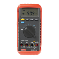
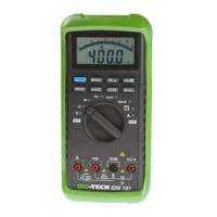
1.2 Front face of meter
Fi
.1 and the followin
numbered list detail the controls and connections present on the front face of the meter.
Before
ou use the tester make sure
ou are thorou
hl
familiar with the settin
s and the connectin
input terminal.
1. Digital display
— The 3200 count di
ital LCD displa
includes a 65-element analo
bar
raph displa
and
automatic annunciators for polarit
, decimal point,
low voltage, AC,
è
, "RANGE", "HOLD" and unit symbols.
2. Rotary function and range switch — This switch is used to select functions and measuring ranges.
3. COM input terminal — Input for the common potential.
4. V-
è
è
-
input terminal — Input terminal for voltage and resistance measurements and diode testing.
5. µA/mA input terminal — Input terminal for measuring currents up to 320mA.
6. A input terminal — Input terminal for measuring currents up to 20A.
7. Manual range button — This button is used for setting and changing ranges manually. Pressing the button once
causes the annunciator "RANGE" to appear on the display. Pressing it repeatedly then sets the meter to the
desired range. To revert to autoranging, hold the button pressed for two seconds.
8. AC/DC,
/
selector button — By pressing this button you can change to a.c. voltage or current in the
voltage or current mode and to continuity or diode testing in the "
-
" mode.