22
GENERAL INFORMATION
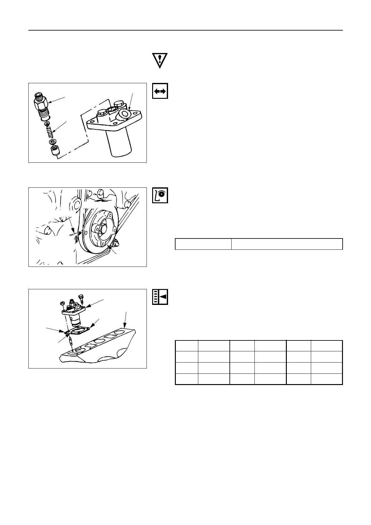
1. Remove the injection pipe of the No. 1 cylinder.
2. Remove the delivery valve holder of the injection
pump of the No. 1 cylinder, and then pull out the
delivery spring.
3. With the spring left removed, install the delivery
valve holder.
4. Slowly turn the crankshaft pulley clockwise, at the
same time, continue to feed the fuel.
When the fuel stop flowing out from the No. 1 deliv-
ery valve holder, stop turning the crankshaft.
This crank angle position is the starting point of
injection.
5. In the condition at Step (4) above, confirm what
degree the “groove mark” of the crank pulley is at,
when seen by the “timing mark”, provided in the
timing gear case.
When the value is out of the range of the normal
injection timing, adjust it accordingly.
Injection pump
Delivery valve
holder
Delivery
spring
Groove mark
TDC mark
Crank
pulley
Timing gear
case cover
(
)
4. INJECTION TIMING
Note:
Take care to avoid entry of dust or foreign particles into
the pump interior when the timing adjustment is made.
* Injection timing BTDC 14°
6. Adjust the injection timing with a shim between the
injection pump and the cylinder block.
Shim is available in the following 9 types, and “iden-
tification mark” is stamped (or imprinted) on the top
face.
Identification mark of shim and its thickness (mm)
Injection pump
Cylinder block
Shim
Identification
mark
Knock hole
Mark Thickness Mark Thickness Mark Thickness
2 0.2 5 0.5 8 0.8
3 0.3 6 0.6 10 1.0
4 0.4 7 0.7 12 1.2
Note:
For each of the injection pumps of three cylinders, the
shim adjustment is made at the same time.
When a shim is missing while overhauling the engine
and the shim thickness is unknown, assemble the
engine with provisional shim inserted. After assembling
the engine, check the injection timing and adjust the
shim until the normal injection timing is obtained.
Reference:
To add the 0.1 mm shim thickness corresponds to the 1
degree of crankshaft angle advance.
Note:
The injection timing varies according to the specifica-
tions of the machine.
Fig. 25
Fig. 26
Fig. 27

 Loading...